1.Description:
ZK-TD4 is a MOS Switch Controller Trigger Delay Module with Timer and Cycle functions.It can work in 16kind work mode with or without trigger signal.It also can be delay a random time in the set range.
2.Features:
1>.16kind work mode
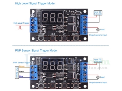
2>.High Level or PNP signal trigger
3>.Power-ON trigger
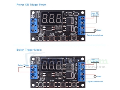
4>.Button switch trigger
5>.400W 15A MOS Driver
6>.Support parameter memory function
7>.Support UART communication function
8>.Optocoupler isolated output
9>.Support forced stop function
10>.Support power saving mode
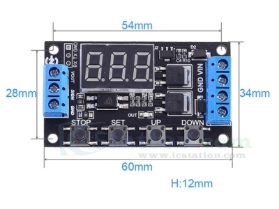
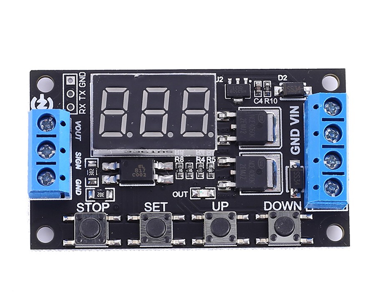
3.Parameters:
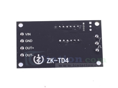
1>.Product Name:ZK-TD4 Trigger Cycle Timer Delay Controller
2>.Product Number:ZK-TD4
3>.Working Voltage:DC 5.0V~30V
4>.Trigger Type:Button/PNP/High Level Signal
5>.Trigger Signal:DC 3.0V~24V
6>.Output Type:Voltage Output(Same to input voltage)
7>.Output Power:400W(Max)
8>.Output Current:15A
9>.Quiescent Current:20mA
10>.Display: 3Bit Red LED Display Screen
11>.Working Temperature range:-40℃~85℃
12>.Working Humidity Range:5%-95%RH
13>.Module Size:60*34*12mm
4.Timing range:
1>.Continuously adjustable from 0.1 seconds to 999 minutes.
2>.Enter the settings interface when short press button ‘STOP’ in the parameter modification interface(Flashing) to select timing range.
3>.Pay attention to the position where the decimal point moves when the button is pressed.
4>.Display ‘XXX.’ The decimal point is the last bit, the timing range is 1 second ~ 999 seconds.
5>.Display ‘XX.X’ The decimal point is the penultimate, timing range is 0.1 second to 99.9 seconds.
6>.Display ‘X.X.X.’ The decimal point is fully lit, timing range is 1 minute to 999 minutes.
7>.For example, if you want to set the OP to 3.2 seconds, move the decimal point to the penultimate position, Screen will display ‘03.2’
8>.OP and CL parameters are the same in different work mode.
9>.It will display OP(CL,LOP) and corresponding delay time by short press button SET in main display interface.
10>.It just display OP and corresponding delay time in P1 mode by short press button SET in main display interface.
5.Parameter Description:
1>.OP:Delay time for turn On;
2>.CL:Delay time Turn OFF;
3>.LOP:Number of cycles.Range is 1-999tims.’----’ means unlimited loop.
4>.CLL:Minimum value of random delay range. The set range is 0.0~99.9second. This CLL parameter just be used for P15 work mode.
5>.CLH:Maximum value of random delay range.The set range is 0.0~99.9second. This CLH parameter just be used for P15 work mode.
6>.SP:Set PWM duty cycle. The set range is 20%,25%,30%,35% to 100%.
6.Work Mode:
1>.Power-ON Trigger Mode:
1.1>.ZK-TD4 will start delay after power on. This mode no need input other trigger signal. The power supply is the trigger signal.
1.2>.P00: Power ON and output keep OFF and start delay time CL. Then turn ON output after delay time CL. E.g. Power ON->OFF->Delay CL->ON.
1.3>.P01: Power ON and output turn ON and start delay time OP. Then turn OFF output after delay time OP. E.g. Power ON->ON->Delay OP->OFF.
1.4>.P02: Power ON and output turn ON and start delay time OP. Then turn OFF output after delay time OP. Keep OFF for delay time CL. Then turn ON output after delay time OL. And then loops the above action.The number of cycles (LOP) can be set. Output will keep OFF after cycle. E.g. Power ON->ON->Delay OP->OFF->Delay CL->cycles->OFF.
1.5>.P03: Power ON and output turn OFF and start delay time CL. Then turn ON output after delay time CL. Keep ON for delay time OP. Then turn OFF output after delay time OP. And then loops the above action.The number of cycles (LOP) can be set. Output will keep ON after cycle. E.g. Power ON->OFF->Delay CL->ON->Delay OP->cycles->ON.
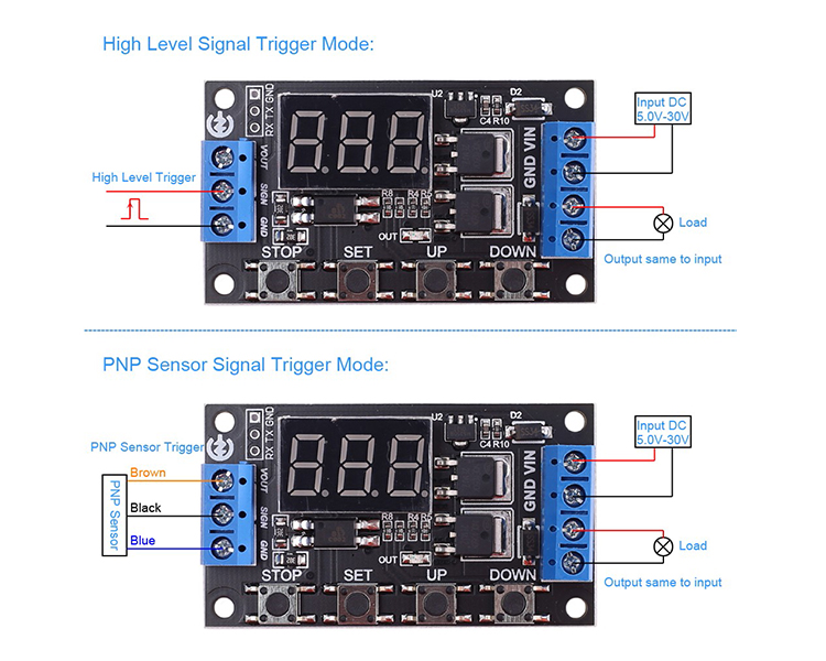
2>.PNP/High Level Signal Trigger Mode:
2.1>.ZK-TD4 will start delay after input trigger. This mode need input trigger signal after provide work power supply.
2.2>.P04: Input trigger signal and output turn ON and start delay time OP. Then turn OFF output after delay time OP. Trigger again is invalid during delay.E.g. Trigger->ON->Delay OP->OFF.
2.3>.P05: Input trigger signal and output turn ON and start delay time OP. Then turn OFF output after delay time OP. Restart delay OP if trigger again during delay.E.g. Trigger->ON->Delay OP->OFF.
2.4>.P06: Input trigger signal and output turn ON and start delay time OP. Then turn OFF output after delay time OP. Stop delay and output turn OFF if trigger again during delay.E.g. Trigger->ON->Delay OP->OFF.
2.5>.P07: Input trigger signal and output keep OFF and start delay time CL. Then turn ON output after delay time CL. E.g. Trigger->OFF->Delay CL->ON.
2.6>.P08: Input trigger signal and output turn OFF and start delay time CL. Then turn ON output after delay time CL. Keep ON for delay time OP. Then turn OFF output after delay time OP. Trigger again is invalid during delay. E.g. Trigger->OFF->Delay CL->ON->Delay OP->OFF.
2.7>.P09: Input trigger signal and output turn OFF and start delay time CL. Then turn ON output after delay time CL. Keep ON for delay time OP. Then turn OFF output after delay time OP. Restart delay OP if trigger again during delay. E.g. Trigger->OFF->Delay CL->ON->Delay OP->OFF.
2.8>.P10: Input trigger signal and output turn OFF and start delay time CL. Then turn ON output after delay time CL. Keep ON for delay time OP. Then turn OFF output after delay time OP. And then loops the above action.The number of cycles (LOP) can be set. Output will keep ON after cycle.Stop delay and output turn ON if trigger again during cycles. E.g. Trigger->OFF->Delay CL->ON->Delay OP->cycles->ON.
2.9>.P11: Input trigger signal and output turn ON and start delay time OP. Then turn OFF output after delay time OP. Keep OFF for delay time CL. Then turn ON output after delay time CL. And then loops the above action.The number of cycles (LOP) can be set. Output will keep OFF after cycle.Stop delay and output turn OFF if trigger again during cycles. E.g. Trigger->ON->Delay OP->OFF->Delay CL->cycles->OFF.
2.10>.P12: Input trigger signal and output turn ON and start delay time OP. Then turn OFF output after delay time OP. Keep OFF for delay time CL. Then turn ON output after delay time CL. And then loops the above action.The number of cycles (LOP) can be set. Output will keep OFF after cycle.Trigger again is invalid during cycles. E.g. Trigger->ON->Delay OP->OFF->Delay CL->cycles->OFF.
2.11>.P13: Keep input trigger signal and output turn ON.Then start delay time OP if remove input trigger.Then turn OFF output after delay time OP.Stop delay and output turn ON if trigger again during delay.
2.12>.P14: Keep input trigger signal and output turn OFF.Then start delay time CL if remove input trigger.Then turn ON output after delay time CL.Stop delay and output turn OFF if trigger again during delay.
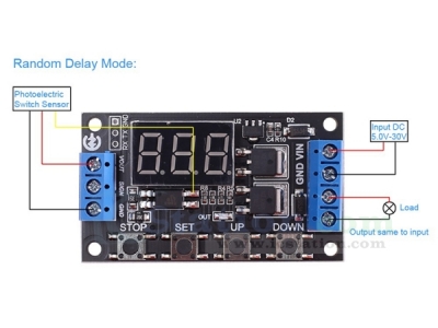
3>.Random Delay Mode:
3.1>.P15: Input trigger signal and output keep OFF and start delay time. The delay time between CLL and CLH. Then turn ON output after delay time CLL~CLH.This mode also can set PWM duty cycle from 20%,25%,30%,35% to 100%. (The delay time is a random value between CLL and CLH. Their setting range is 0.0~99.9second and CLH is more than CLL.) E.g. Trigger->OFF->Delay->ON.
7.Set steps:
1>.Confirm the working mode before start to set mode and parameters.
2>.Keep press SET Button about 2second enter to select work mode.
3>.Press UP and Down button to switch work mode P00~P015.
4>.Press SET button to set parameter value for selected work mode such as P03 work mode.
5>.The first set parameter OP will flashing about 2second and display parameter value.
6>.Press STOP button to move the decimal point and set delay time range.
7>.Press UP and Down button to set OP parameter value.
8>.Press SET button to set the second parameter value CL. Then set time range and parameter value as the same method.
9>.Press SET button to set the third parameter value LOP. Then set parameter as the same method. Note:’----’ means unlimited loop.
10>.For P15 work mode the set method is the same for CLL, CLH and SP. Note: The delay time is 0.0~99.9second at this mode.
11>.Keep press SET Button about 2second to save parameter and exit set mode to start normal work.
8.Additional Features:
1>.Auto sleep function: keep press button 'STOP' about 2second in the normal running interface to turn on or off auto sleep function.
1.1>C-L:Turn ON auto sleep function.Screen will automatically turns off if there is no operation within 3 minutes.It can be wake up by any buttons.
1.2>.O-d:Turn OFF auto sleep function.
2>.Enabled/Disabled output by press button STOP:
2.1>.ON:Enabled output during delay time OP.
2.2>.OFF:Disabled output.Module can not output any signal at this mode.
9.Use Steps:
1>.Connect right work voltage from input terminal.
2>.Set work mode and parameter value.
3>.Remove work power supply.
4>.Connect Load and trigger signal if need.
5>.Re connect the power supply.
6>.Start normal work with or without in trigger signal by selected work mode.
10.Note:
1>.It can output voltage.The output voltage is same to input voltage.
2>.It will display ‘000’ if stop work.It shows the decimal point when working.
3>.The VIN and OUT+ are connected in the internal circuit.
4>.The GND and OUT- are not connected in the internal circuit. Users cannot connect GND and OUT- together.Otherwise, module will keep the output.
5>.Please read use manual and description before use.
11.Application:
1>.Delay switching
2>.Counter
3>.Access control system
4>.Car circuit modification
5>.Motor
6>.The electromagnetic valve
7>.Light strip
12.Package:
1pcs ZK-TD4 Trigger Cycle Timer Delay Controller


.JPG)