- prev
- next
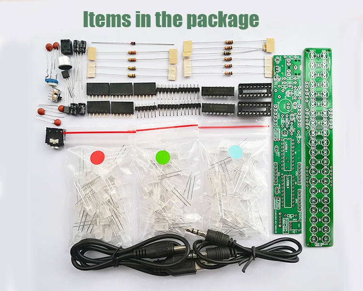
DIY Kit DC 3V-12V Audio Spectrum Indicator 5mm Red/Green/Blue LED LM3914 Level Indicator Kit
$5.31$7.5930%
00d : 00h : 00m : 00s
Item ID: GY18600
Product Details
1.Introduction:
FED-201 is a Audio Spectrum Indicator DIY Kit.
It can display in Red/Green/Blue according to the input audio signal from microphone.
It can be used to display the intensity of audio.
The number of LED displayed changes according to the intensity of the audio.
2.Feature:
1>.40pcs highlight LED
2>.Simple circuit to learn
3>.Automatic flashing
4>.DIY soldering project
5>.Adjustable sensitivity
3.Parameter:
1>.Product Name:FED-201 Audio Spectrum Indicator DIY Kit
2>.Product Number:FED-201
3>.Work Voltage:DC 3V-12V
4>.Work Current:120mA
5>.Power Type:3.5mm Power Socket
6>.Work Module:Switch Control
7>.Color:Red+Green+Blue LED
8>.Work Temperature:-40℃~85℃
9>.Work Humidity:5%~85%RH
10>.Size(Installed):142x22x30mm
5.Installation Steps (Please be patient):
.png)
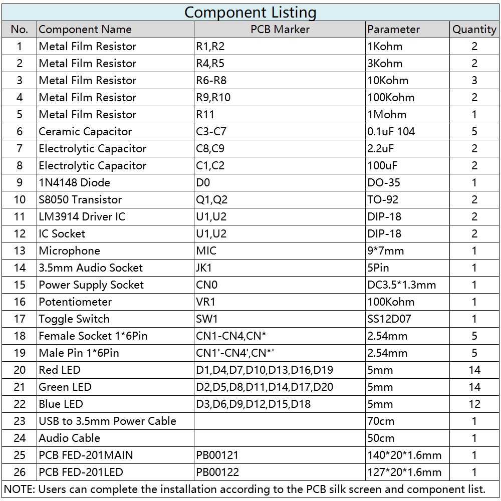
Step 1: Install 1pcs DO-35 1N4148 Diode at D0.The black mark is negative pole.
Step 2: Install 2pcs 1Kohm Metal Film Resistor at R1,R2.
Step 3: Install 2pcs 3Kohm Metal Film Resistor at R4,R5.
Step 4: Install 3pcs 10Kohm Metal Film Resistor at R6-R8.
Step 5: Install 2pcs 100Kohm Metal Film Resistor at R9,R10.
Step 6: Install 1pcs 1Mohm Metal Film Resistor at R11.
Step 7: Install 5pcs 0.1uF 104 Ceramic Capacitor at C3-C7.
Step 8: Install 1pcs DIP-18 IC Socket at U1,U2. There is a mark on one end of the IC Socket and there is a mark on PCB where the IC can place on. These two marks are corresponding to each other and are used to specify the installation direction of the IC Socket.
Step 9: Install 1pcs DC3.5*1.3mm Power Supply Socket at CN0.
Step 10: Fix the power socket with the extra pins of the resistor.
Step 11: Install 1pcs 5Pin 3.5mm Audio Socket at JK1
Step 12: Install 2pcs TO-92 S8050 Transistor at Q1,Q2.
Step 13: Install 2pcs 100uF Electrolytic Capacitor at C8,C9.
Step 14: Install 2pcs 2.2uF Electrolytic Capacitor at C1,C2. Pay attention to distinguish between positive and negative.The Longer pin is positive pole.The longer pin is inserted into the rectangular pad.
Step 15: Install 1pcs 9*7mm Microphone at MIC1.The marked pin is negative pole.
Step 16: Install 5pcs 2.54mm Female Socket 1*6Pin at CN1-CN4,CN*.
Step 17: Install 1pcs DIP-18 LM3914 Driver IC at U1,U2.There is a mark on one end of the IC and there is a mark on PCB where the IC can place on.These two marks are corresponding to each other and are used to specify the installation direction of the IC.
Step 18: Install 1pcs SS12D07 Toggle Switch at SW1.
Step 19: Install 1pcs 100Kohm Potentiometer at VR1.
Step 20: The longer pin is inserted into the rectangular pad(positive pole). The shorter pins are inserted into the oval pads.
Step 21: Install 14pcs 5mm Red LED at D1, D4,D7,D10,D13,D16,D19 and D1’, D4’, D7’, D10’, D13’, D16’, D19’.
Step 22: Install 14pcs 5mm Green LED a D2, D5, D8, D11, D14, D17, D20 and D2’, D5’, D8’, D11’, D14’, D17’, D20’.
Step 23: Install 12pcs 5mm Blue LED a D3, D6, D9, D12, D15, D18 and D3’, D6’, D9’, D12’, D15’, D18’.
Step 24: Install 5pcs 2.54mm Male Pin 1*6Pin at CN1-CN4,CN*.
Step 25: Assemble 2pcs PCB.
Step 26: Connect to power supply and enjoy the effect.