- prev
- next
DIY Kit Red Blue Dual-Color Flashing Light Analog Traffic Signal Indicator Soldering Practice Tranining Kit
$4.61$6.5930%
00d : 00h : 00m : 00s
Item ID: GY18599-1
Product Details
1.Introduction:
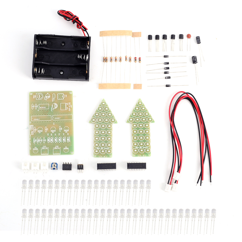
BSD-50 Dual-Color Flashing Light DIY Kit is a flash kit consists of circuit board and allows 50pcs LED flash alternately.
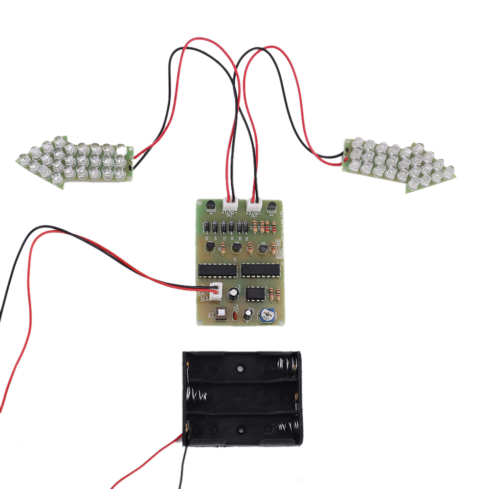
It can simulate the traffic signal indicator which is very helpful for beginners to understand the circuit principle.
2.Feature:
1>.50pcs highlight LED
2>.Perfect simple circuit
3>.Automatic flashing
4>.Comes with battery box
3.Parameter:
1>.Product Name:BSD-50 Dual-Color Flashing Light DIY Kit
2>.Product Number:BSD-50
3>.Work Voltage:DC 3V~6V
4>.Work Current:50mA
5>.Power Type:Battery Box
6>.Work Module:Switch Control
7>.Color:REd+Blue LED
8>.Flashing Speed:Adjustable
9>.Flashing Mode:Left 4times => Right 4times => All 4times
10>.Work Temperature:-40℃~85℃
11>.Work Humidity:0%~95%RH
12>.Main PCB Size(Installed):66*45*13mm
13>.LED PCB Size(Installed):61*29*11mm
4.Application:
1>.Training welding skills
2>.Student school
3>.DIY production
4>.Project Design
5>.Electronic competition
5.Installation Tips:
1>.User needs to prepare the welding tool at first.
2>.Please be patient until the installation is complete.
3>.The package is DIY kit.It need finish install by user.
4>.The soldering iron can't touch the components for a long time(1.0 second), otherwise it will damage the components.
5>.Pay attention to the positive and negative of the components.
6>.Strictly prohibit short circuit.
7>.User must install the LED according to the specified rules.Otherwise some LED will not light.
8>.Install complex components preferentially.
9>.Make sure all components are in right direction and right place.
10>.Check that all of the LED can be illuminated.
11>.It is strongly recommended to read the installation manual before starting installation!!!
12>.Please wear anti-static gloves or anti-static wristbands when installing electronic components.
6.Installation Steps(Please be patient):
Step 1: Install 2pcs 22ohm Metal Film Resistor at R8,R9.
Step 2: Install 7pcs 1Kohm Metal Film Resistor at R1-R7.
Step 3: Install 6pcs DO-41 1N4007 Diode at D1-D6.The white mark is negative pole.
Step 4: Install 1pcs 0.1uF 104 Ceramic Capacitor at C3.
Step 5: Install 2pcs DIP-16 CD4017 at U2,U3.There is a dot on one end of the IC and there is a mark on PCB where the IC can place on.These two marks are corresponding to each other and are used to specify the installation direction of the IC.
Step 6: Install 3pcs XH2.54-2P Male Socket at CN1-CN3.
Step 7: Install 1pcs DIP-8 NE555 at U1.There is a dot on one end of the IC and there is a mark on PCB where the IC can place on.These two marks are corresponding to each other and are used to specify the installation direction of the IC.
Step 8: Install 5pcs TO-92 S8050 Transistor at Q1-Q5.
Step 9: Install 1pcs 100uF Electrolytic Capacitor at C1.Pay attention to distinguish between positive and negative.The Longer pin is positive pole.The longer pin is inserted into the rectangular pad.
Step 10: Install 1pcs 10uF Electrolytic Capacitor at C2.Pay attention to distinguish between positive and negative.The Longer pin is positive pole.The longer pin is inserted into the rectangular pad.
Step 11: Install 1pcs 5.8*5.8mm Self-locking Switch at SW1.There is a concave on switch and there is a white mark on PCB where the switch can place on.These two marks are corresponding to each other and are used to specify the installation direction of the switch.
Step 12: Install 1pcs 100Kohm Potentiometer at VR1.
Step 13: The longer pin is inserted into the rectangular pad(positive pole). The shorter pins are inserted into the oval pads.
Step 14: Install 25pcs Green LED on one light PCB and 25pcs Yellow LED on another light PCB .
Step 15: Install wire to 3pcs PCB.Red wire connects to positive pole and Black wire connects to negative pole.
Step 16: Connect to power supply and enjoy the effect.