- prev
- next
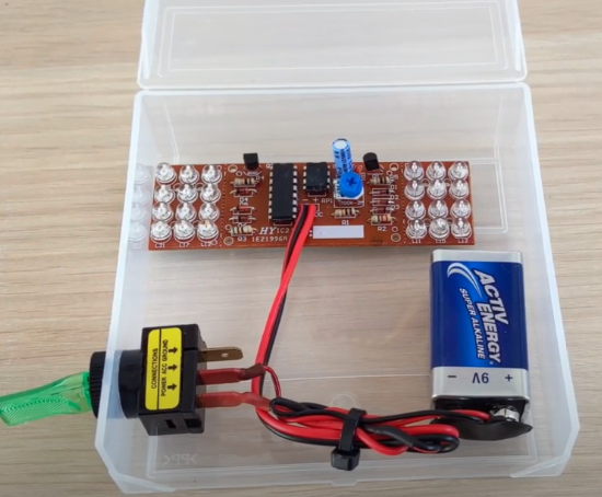
Red Blue Dual Colors Strobe Flashing Light DIY Kits for Soldering Practice Learning
| Quantity | 5+ | 30+ | 50+ |
| Price | $1.70 | $1.35 | $1.10 |
Product Details
Please note: The PCB color has been changed to Green since Feb, 2023. All the other components are as the same as before.
Features:
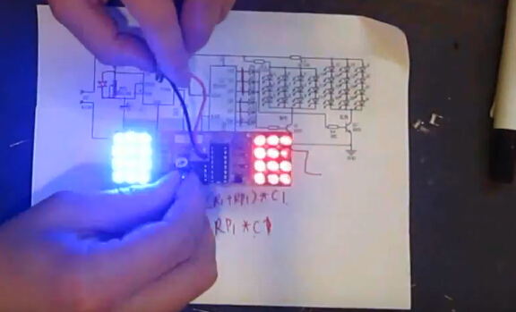
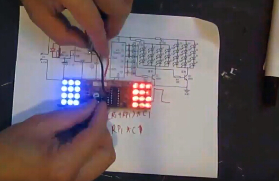
1. This kit uses NE555 CD4017 chips and circuit simulation lights, blue LED and red LED flash alternately according to the pulse respectively, adjusted RP1 adjustable blinking frequency.
2. The circuit voltage is DC9V-12V, these diy kits don't contain battery.
3. The kit is simple to use and interesting, it's suitable for electronics enthusiasts and students beginners to practice assembly.
Circuit Board Characteristics:
1. It adopts 1.5mm electric board and thicker wire. The layout of the components is beautiful.
2. The optimization design was carried out for special training, convenient to repeat desoldering, so it could improve the efficiency in the use.
3. Red flashing lights and blue flashing lights are in separately board. If you need to separate installation to other places or increase the distance, can move off from stamp hole, and then through the two wires connected to the motherboard, so you can install it to any other place.
Working Principle:
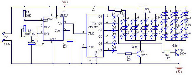
1. The kit multivibrator composed by NE555 and CD4017 decade counter / pulse distributor components.
2. When 1,3,5 pulse arrival, Q0, Q2, Q4 sequentially output high, the blue LED flashes three times,
the first 6,8,10 pulse arrival, Q5, Q7, Q9 sequentially output high level, the red LED flashes three times, when the arrival of the first pulse 13, 15 and then the blue LED flashes in cycles alternating blue and red LED flashes to form a simulated lights look.
3. RP1 can be changed to change the size of the oscillation period, thus changing the blinking speed of the LED, the whole circuit can be operated DC9-12V.
Tested by ICStation's Outstanding Partner Kerry Wong:
(Please noted: The PCB color has been changed to Green since Feb, 2023. )
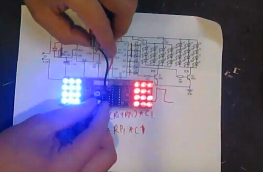
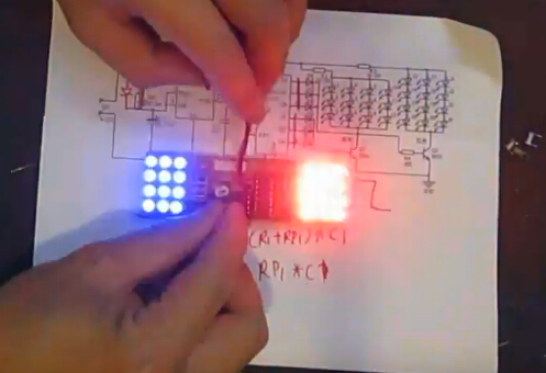
Learn More Details in the Video:
(The language in the video is English)
Tested by ICStation's Little Customer Alex: