
- prev
- next
DIY Clap On Off Switch Kit Electronics Soldering Practice Set Clap Switch DIY Kits
$2.09$2.9930%
| Quantity | 10+ | 30+ | 50+ | 100+ |
| Price | $1.90 | $1.75 | $1.50 | $1.35 |
00d : 00h : 00m : 00s
Item ID: 1755
Product Details
Description:
Package name: clap switch kit
Kit Model: PSK-1
Operating voltage: 5V
PCB size: 28 x 49mm
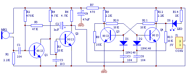
Principle of Circuits
- ▲The circuit is maily composed by audio frequency and bistable tigger circuit. Q1 and Q2 form the secondary amplifier circuit.
- ▲Audio signal which accepted by MK1 enters to Q1 base through the coupling of C1, and enters to Q2 base through collector directly after amplified.
- ▲It will obtain a negative square-wave which used to trigger the bistable circuit from Q2's collector.
- ▲R1 and C1 restrict the frequency response of circuit to 3kHz which is in a high sensitivity range.
- ▲Q4 is cutoff, while Q3 is saturated and D3 is off when the power is on.
- ▲When MK1 obtains the control signal, a negative square-wave has been outputted after amplified and negative pluse has been added to Q3 base through D1 after differentiation processing.
- ▲The power flips rapidly and D3 is lighted at this time. The power flips again when MK1 obtains the control signal at the second time. And the D3 is off.
- ▲A cable terminal J1 can be added on PCB which used for connecting external control equipment. It can realize the sound control function on other equipment by connecting J1 and relay.(A diode should be connected reversely at the ends of relay when connecting the relay)
- ▲This circuit is with 5V power supply. LED is off when the machine current 3 mA, while the LED is on when the current is 6 mA.
Circuit Diagram:
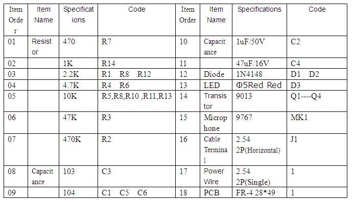
List of Components:
Reviewed by arduinoLab:
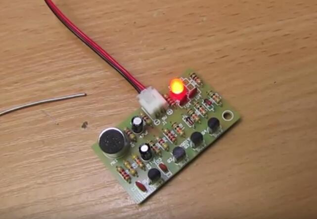
Enjoy video here


