
- prev
- next
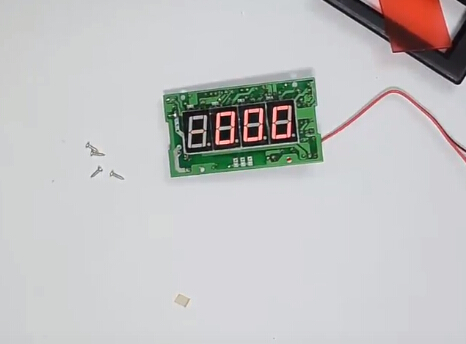
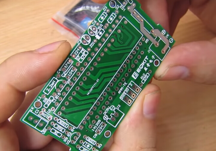
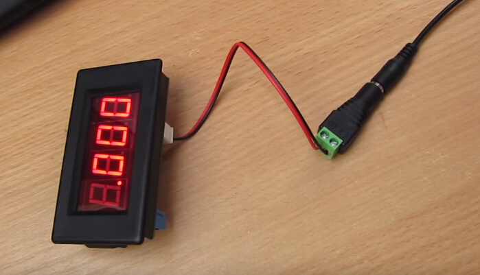
DIY 4-Digit Red Digital Ammeter Kit ICL7107 DC 5V 35mA Ammeter DIY Soldering Kit
| Quantity | 10+ | 30+ | 50+ |
| Price | $4.15 | $3.99 | $3.70 |
Product Details
Product Introduction:
1.Model: AMM-TE
2.PCB Size: 70.6*39mm
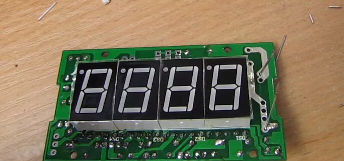
3.Display Window Size: 51*24mm
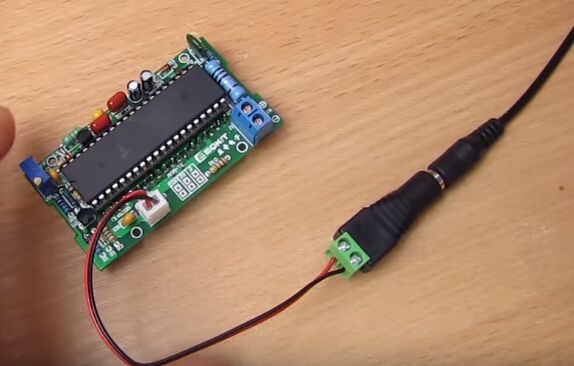
4.Operating Voltage: DC 5V
5.Operating Current: 35mA
6.Measurement Precision: +/-1mA
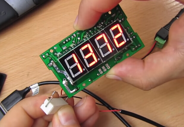
7.Measurement Range: 0-2A
8.Overrange Display: the first bit displays 1 or -1
9.Display Color: Red
Packing List:
| Name | Specification | Code | Quantity |
| Metal Film Resistor | 0.1 ohm/2W | R5 | 1 |
| Metal Film Resistor | 2K ohm | R1,R9 | 2 |
| Metal Film Resistor | 56K ohm | R2 | 1 |
| Metal Film Resistor | 1M ohm | R6 | 1 |
| Metal Film Resistor | 100 ohm | R3 | 1 |
| Metal Film Resistor | 270 ohm | R10 | 1 |
| Metal Film Resistor | 20K ohm | R8 | 1 |
| Metal Film Resistor | 47K ohm | R7 | 1 |
| Metal Film Resistor | 100K ohm | R4 | 1 |
| Monolithic Capacitor | 100pF | C1 | 1 |
| Monolithic Capacitor | 0.1uF | C8 | 1 |
| Monolithic Capacitor | 0.47uF | C4 | 1 |
| CBB Capacitor | 0.1uF | C2 | 1 |
| CBB Capacitor | 0.22uF | C5 | 1 |
| Polyester Capacitor | 0.01uF | C3 | 1 |
| Electrolytic Capacitor | 10uF/25V | C6,C7 | 2 |
| Diode | IN4148 | D1,D2,D3 | 3 |
| Stabilivolt Diode | ST5V1 | ZD1 | 1 |
| Triode | C1815 | Q1 | 1 |
| Inductor | 2.2mH | L1 | 1 |
| Digital Tube | 1 bit Common Anode Red | DS1-DS4 | 4 |
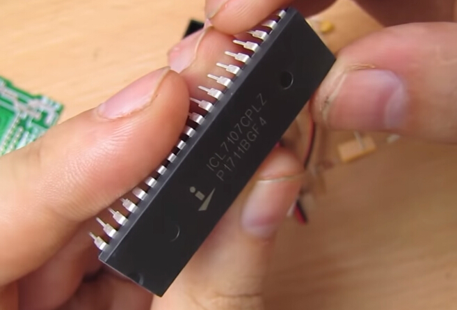
| IC | ICL7101 | U1 | 1 |
| IC | TL431A | U2 | 1 |
| Potentiometer | 3296 1K ohm | VR1 | 1 |
| IC Socket | 40P | U1 | 1 |
| Connection Terminal | 2P | J2 | 1 |
| Connection Terminal | 301-2P | J1 | 1 |
| Power Wire | 2P Single Head | 1 | |
| PCB | 70.6*39mm | 1 | |
| Filter Board | 1 | 1 | |
| Shell | 79*43mm | 1 | |
| Screw | M1.7*6mm | 4 |
Circuit Diagram:
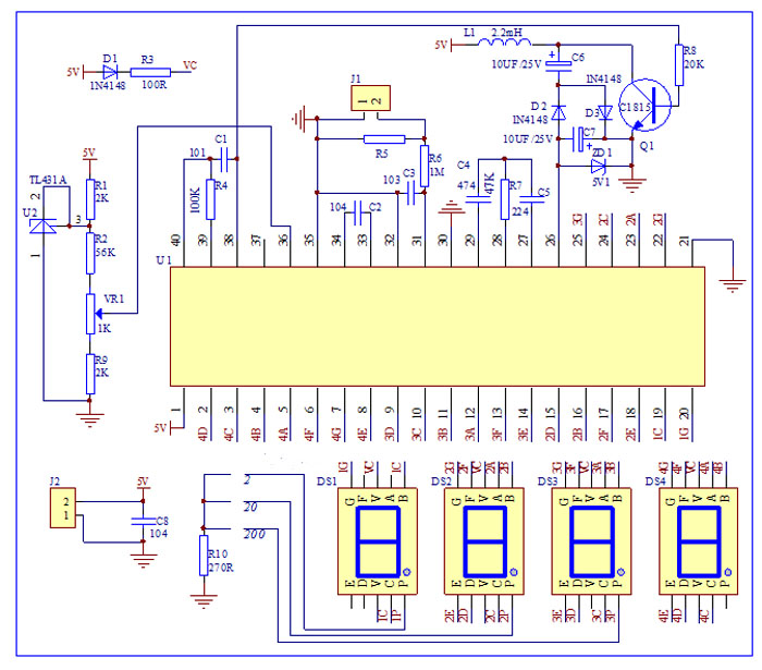
Circuit Principle:
AMM-TE ammeter is mainly composed of ICL7107, power circuit, reference voltage source,
input circuit and display circuit.
▲1. ICL7107 is a BCD output integral type A/D conversion chip, its internal includes; linear amplification, analog switch, oscillation, display driving etc.
▲2. Power circuit is divided into positive power and negative power; positive power is input by J2,C8 filtering; negative is composed of R8,Q1,L1,C6,C7,D2,D3 and ZD1, and generate -5V voltage is input by chip 26th pin.
▲3. Reference voltage source is composed of R1,R2,VR1,R9 and U2; 36-pin is reference voltage input pin; adjust VR1 potentiometer to let 36-pin voltage be 100mV.
▲4. Input circuit is composed of J1,R5,R6 and C3. When the current of measured circuit passes through R5, it will generate a voltage on R5; this voltage will be input to chip 31-pin through R6 current limiting and be processed; C3 is input voltage filtering capacitor.
▲5. Display circuit is composed of DS1-DS4,D1,D4;4 digital tubes can be drived directly by the chip, R10 is current limiting resistance of DS1-DS3 digital tubes decimal points.
Finished Product Debugging:
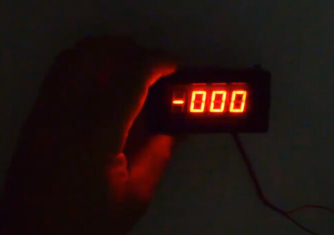
1. After connecting with DC 5V (please notice the polarity), the digital tube will display -.000 or .000,this is normal.
2. Use multimeter to measure the voltage between chip 36-pin and 35-pin,and adjust VR1 potentiometer let it be 100mV
Key Points Voltage Reference Value:
1.Chip 1-pin and 21-pin voltage 5V
2.Chip 36-pin and 21-pin voltage 100mV
3.Chip 26-pin and 21-pin voltage -5V
I. Tested by ICStation's Outstanding Partner ELECTROJUANYU:
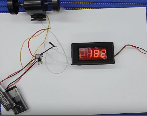
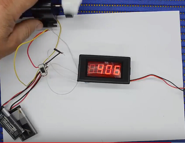
Learn More Details in the Video:
(The language in the video is Spanish)
II. Tested by ICStation's Outstanding Partner arduinoLab:
Learn More Details in the Video:
(The language in the video is Russian)


