- prev
- next
Dual Frequency RFID Reader Writer Wireless Module UART 13.56MHz 125KHz for IC/ID Card
Product Details
Description:
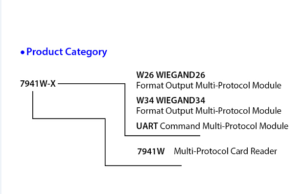
7941W is a multi-protocol dual-band read and write module. Set IC and ID read and write one.
It can read a variety of IC and ID card. Support Mifare1K, UID card, IC card, T5577 ID card.
Features:
1>. Voltage: DC 5V
2>. Current: 50mA
3>. Distance: Mifare>3cm; EM>5cm
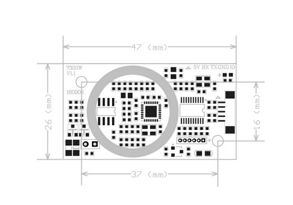
4>. Size: 47mmX26mmX5mm
5>. Interface: UART, Wiegand
6>. Support Chips: ISO/IEC 14443 A/MIFARE, NTAG, MF1xxS20, MF1xxS70, MF1xxS50
7>. EM4100, T5577 read and write function
8>. Operating Temperature: -25~85 Celsius
Connection Introduction:
1>.5V: DC 5V power supply pin; if you use linearity power, it will gain better effects
2>.RX: receive pin
3>.TX: transmit pin
4>.GND: power supply ground pin
5>.IO: definition
Protocol Introduction: (UART serial port communication protocol is shown as below)
| Sending Protocol: | |||||
| Protocol Header | Address | Command | Data Length | Data | XOR Check |
| AB BA | 1 Byte | 1 Byte | 1 Byte | 1-255 Byte | 1 Byte |
| Receiving Protocol: | |||||
| Protocol Header | Address | Command | Data Length | Data | XOR Check |
| CD DC | 1 Byte | 1 Byte | 1 Byte | 1-255 Byte | 1 Byte |
1>. Protocol Header: send (0xAB 0xBA)
2>. Return: (0xCD 0xDC)
3>. Address: default 0x00
4>. Command:
Send:
1). 0x10 read UID number
2). 0x11 write UID number (4 bytes), use default password ffffffffffff
3). 0x12 read specified sector
4). 0x13 write specified sector
5). 0x14 modify the password of group A or group B
6). 0x15 read ID number
7). 0x16 write T5577 number
8). 0x17 read all sector data (M1-1K card)
Return:
1).0x81 return operation succeeded
2).0x80 return operation failed
5>. Data Length: means following data length; if it’s 0, then the following data will not occur.
6>. Data: read and written data
Sending Data:
1). Read Specified Sector: the first byte of the data represents sector; the second byte means the certain block of the sector; the third byte means A or B group password (0x0A/0x0B);
then it comes with password of 6 bytes.
2). Write Specified Sector: the first byte of the data represents sector; the second byte means the certain block of the sector; the third byte means A or B group password (0x0A/0x0B);
then it comes with password of 6 bytes and block data of 16 bytes.
3). Modify Password: the first byte means the certain sector; the second byte means A or B group password (0x0A/0x0B); then it comes with old password of 6 byte and new password.
Receiving Data:
Read specified sector return data format, the first byte is sector; the second byte is the certain block of sector; then it comes with block data of 16 bytes.
7>. XOR check: result of other bytes check except protocol header.
Example:
AB BA 00 10 00 10
AB BA 00 11 04 6D E9 5C 17 DA
AB BA 00 12 09 00 01 0A FF FF FF FF FF FF 10
AB BA 00 13 19 00 01 0A FF FF FF FF FF FF 00 01 02 03 04 05 06 07 08 09 01 02 03 04 05 06 07
AB BA 00 14 0E 00 0A FF FF FF FF FF FF 01 02 03 04 05 06 17
AB BA 00 15 00 15
AB BA 00 16 05 2E 00 B6 A3 02 2A
AB BA 17 07 0A FF FF FF FF FF FF 1A
Applications:
1>.Attendance Fingerprint Read Write Module
2>.Entrance Guard Intercom Read Write Module
3>.Replicator
Module Size: