
- prev
- next
DIY Kit Electronic Doorbell NE555 Electronic Production Transformer Sound Circuit Processing Board
$1.39$1.9930%
| Quantity | 10+ | 30+ | 50+ |
| Price | $1.39 | $1.35 | $1.20 |
00d : 00h : 00m : 00s
Item ID: 13092
Product Details
Description:
- ▲It is composed of a time base circuit integrated block and peripheral components. It has a beautiful sound quality, easy to install, low cost and low power consumption.
- ▲The kit is a circuit for a bell that can make "ding, dong" sound.
- ▲Its working voltage is DC3V-12V.
- ▲It is usually powered by a 9V laminated battery. The higher the voltage, the louder the sound.
- ▲Since the speaker is not in the box, the sound phase in the front and back of the plate counteracts the volume and the volume is smaller. You can load the carton to raise the volume.
Working Principle:
- ▲The core C1 is the time base circuit integrated block NE 555. It forms the unsteady multivibrator.
- ▲Press the button AN (mounted on the door), the oscillator oscillates, the oscillation frequency is about 700Hz, and the speaker makes a "ding" sound.
- ▲At the same time, the power supply is charged by diode D1 to C1.When the button is released, C1 is discharged through the resistance R1, maintaining the oscillation.
- ▲However, due to the disconnection of AN, the resistance R2 is threaded into the circuit, which changes the oscillation frequency, about 500Hz, and the speaker makes a "dong" sound.Until the voltage on C1 can't sustain the 555 oscillation.
- ▲ The length of the sound of "dong" can be changed by changing the number of C1.
Note:
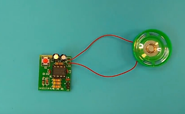
- ▲The kit circuit is fairly simple. You will get a about 5*7cm universal board or process PCB board.
- ▲Due to the cost limitation, the loudspeaker will be a little rusty for the inventory. (and different batches may not be the same, generally 23-50mm speakers). However, it does not affect the use and experimental effect. If you mind, please select a new product.
Circuit Diagram:
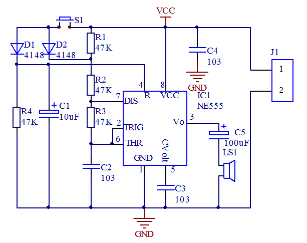
Component Listing:
| NO. | Component Name | PCB Marker | Parameter | QTY |
| 1 | Metal Film Resistor | R1-R4 | 47K | 4 |
| 2 | Ceramic Capacitor | C2-C4 | 0.01uf | 3 |
| 3 | 1N4148 | D1-D2 | 2 | |
| 4 | Electrolytic Capacitor | C1 | 10uf | 1 |
| 5 | Electrolytic Capacitor | C5 | 100uf | 1 |
| 6 | Button | S1 | 1 | |
| 7 | NE555 | IC1 | DIP-8 | 1 |
| 8 | Cable | 7cm | 4 | |
| 9 | Speaker | 8ohm 0.5W | 1 | |
| 10 | PCB | 27*25mm | 1 |
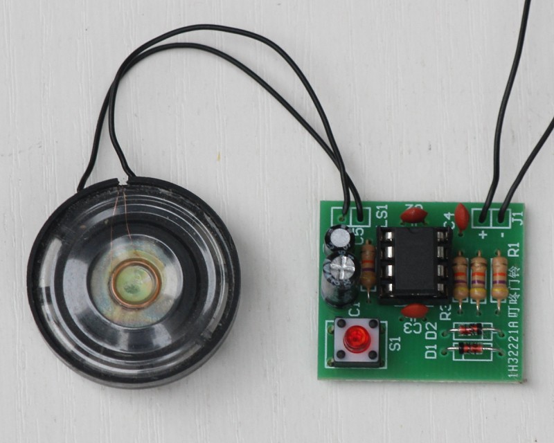
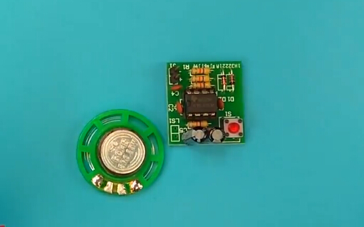
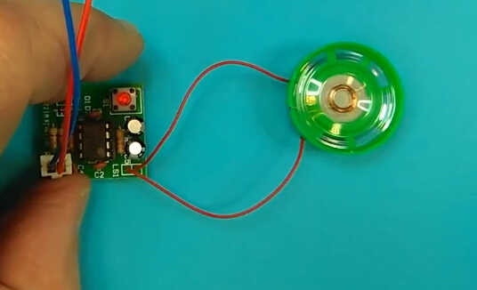
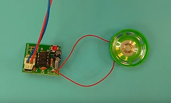
Finished Product Picture:
(Note: Blow picture is just for reference, the color of the buzzer is slightly different, functions are the same, please kindly noted.)
Tested by ICStation's Outstanding Partner bzoli5706:
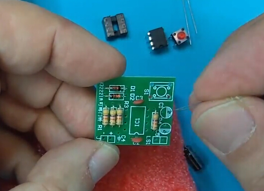
Learn More Details in the Video:
(You could hear some sound in the video, hope you enjoy the kits. ^_^)


