
- prev
- next
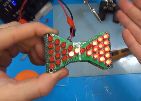
DIY Kit Red LED Electronic Hourglass Shaped Flashing Light DC 3.3V-5V Funny Electronic Soldering Kits
| Quantity | 10+ | 30+ | 50+ | 100+ |
| Price | $3.25 | $3.00 | $2.85 | $2.70 |
Product Details
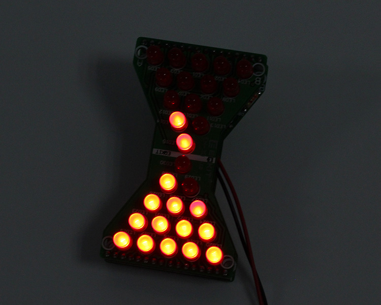
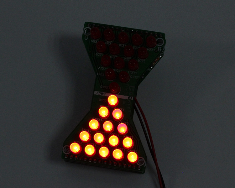
DIY Kit Red LED Hourglass Shaped Flashing Light
Parameters:
| No. | Parameter | Value |
| 1 | Name | Electronic hourglass |
| 2 | Model | EH-30 |
| 3 | Working Voltage | DC 3.3-5V |
| 4 | Shape Size | 74.4*43.7*24mm |
| 5 | Hourglass Speed | Adjustable |
| 6 | Packing Weight | 34g/kit |
| 7 | LED Color | Red |
Tools you need:
1>. Iron (30W)
2>. Solder wire
3>. Multimeter
4>. Tweezers
5>. Wire cutters
Precautions:
1>. Check part values & quantities against part list.
2>. Always meter resistors values before soldering.
3>. Understand all part polarities and orientations.
Component list:
| No. | Name | Parameter | QTY |
| R1-R30. R32. R33 | RES | 3.3K | 32 |
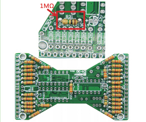
| R31 | RES | 1M | 1 |
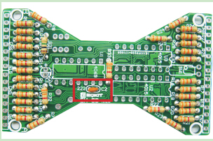
| C2 | CAP | 222P | 1 |
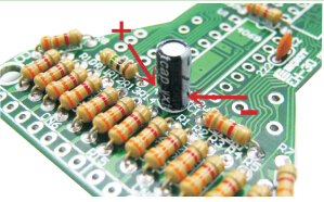
| C1 | E-CAP | 22uF | 1 |
| LED-LED30 | LED | 5mm | 30 |
| U1 | IC | 4069 | 1 |
| U2. U3 | IC | 4015 | 2 |
| SW1 | Direction switch | SW300DA | 1 |
| S1 | Power switch | 6P Auto lock | 1 |
| VR1 | ADJ-RES | 100K | 1 |
| CN1-CN4 | Connector | 8P | 4 |
| CN5-CN8 | Connector | 8P | 4 |
| / | PCB | EH-30-MAIN | 1 |
| / | PCB | EH-30-LED | 1 |
Installation steps:
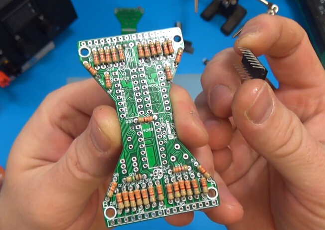
1>. Install MIAN RES: R31=1 M ohms; Other resistors are 3.3K ohms
2>. Install CAP: C2=222P
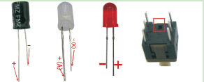
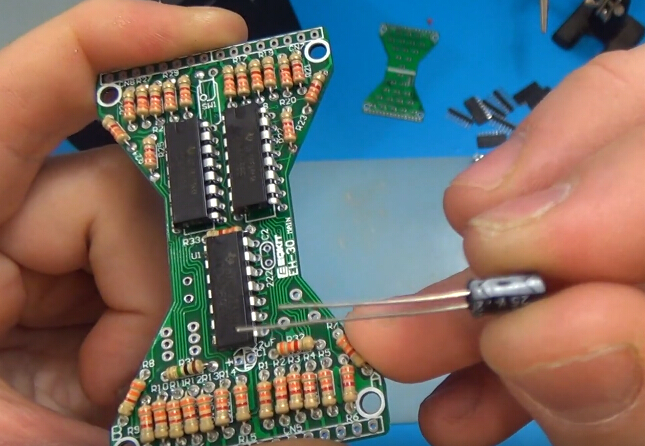
3>. Install E- CAP: C1=22uF, Notice that the positive electrode of electrolytic capacitor can not be reversed.
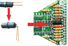
4>. Install Directional switch. Bend the switch 90 degrees, and then install it to SW1.
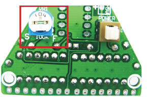
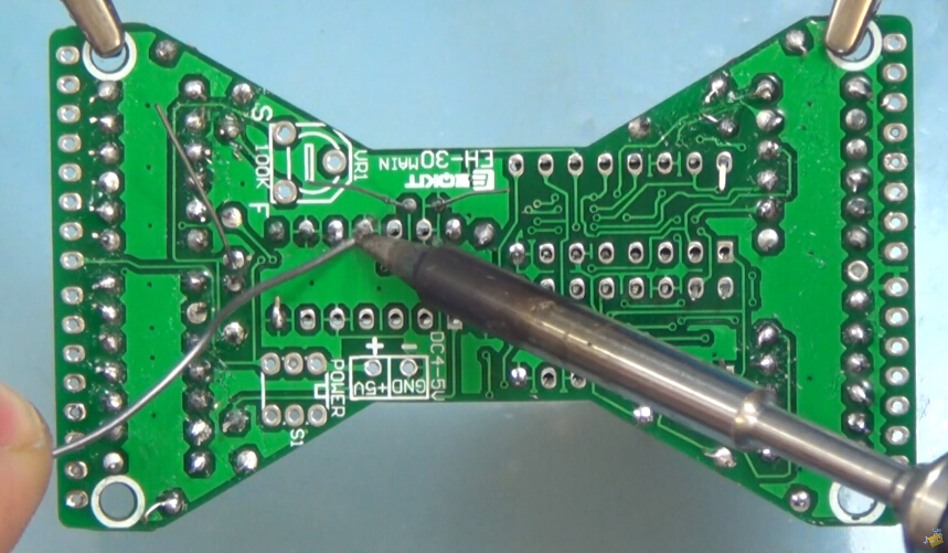
5>. Install ADJ-RES:
VR1=104K. Note that the adjustable resistance should be soldered to the back of the circuit board.
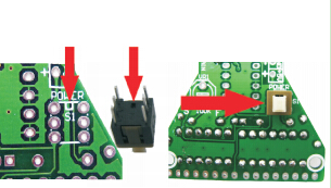
6>. Install power switch:
Pay attention to the installation direction installation direction of the switch.
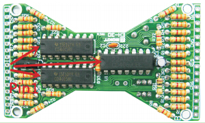
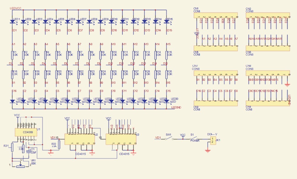
7>. Install IC:
Pay attention to the installation direction of the IC. U1=CD4069. U2=U3=CD4015.
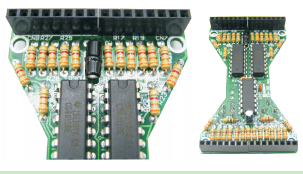
8>. Install 8pin Connector:
Refer to the picture below, install connector to CN5, CN6, CN7,CN8.
9>. Install LED panel:
Install 30 LED on the circuit board. The long foot is the positive pole. Install on the rectangle pad.
10>. Install pin connector:
Install the short side of the connector to the back of the circuit board.
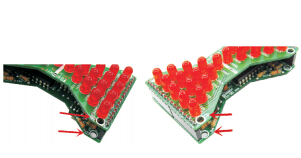
11>. Install main and LED:
Install the motherboard and LED gently press together A point to A, B point to B.
12>. Soldering power cable:
Red line is positive power supply DC5V suitable for USB. 3 section AA or AAA battery box.
Warm Tips:
Light- emitting diode and electrolytic capacitor the longer pin is it the anode it should be installed on the rectangle pad of PCB. Refer to the picture below:
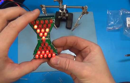
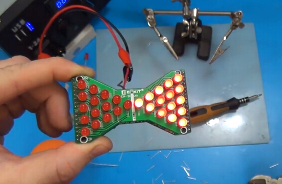
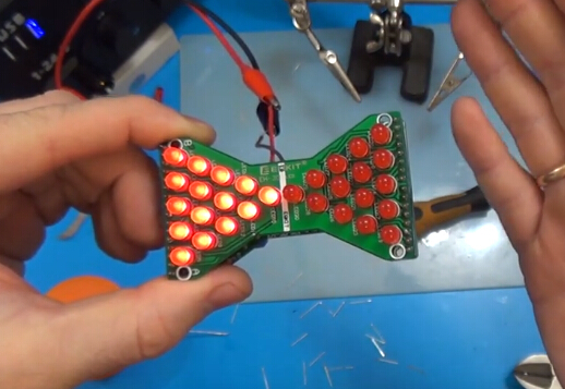
Finished Product Picture:
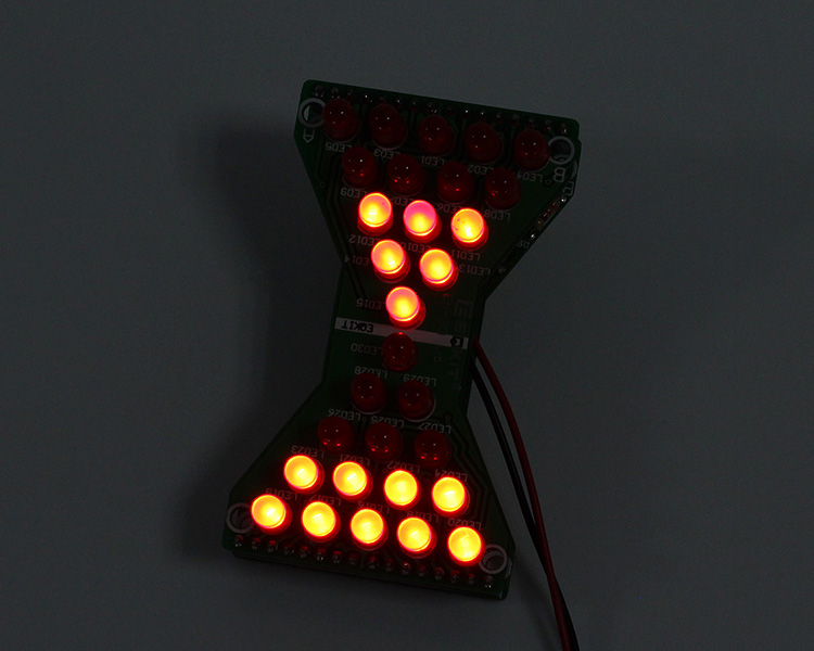
Tested by ICStation's Outstanding Partner OnlyKit.:
Learn More Details in the Video:
(The language in the video is Russian)


