
- prev
- next
60W High-Power Adjustable Buck-Boost Power Supply Module Step Up Down Converter LCD Display
$11.61$16.5930%
00d : 00h : 00m : 00s
Item ID: 13753
Product Details
Please kindly noted:
This is not the assembled one. You need to install the kits. Simple and easy. Feel free to contact us if there is any question.
1.Description:
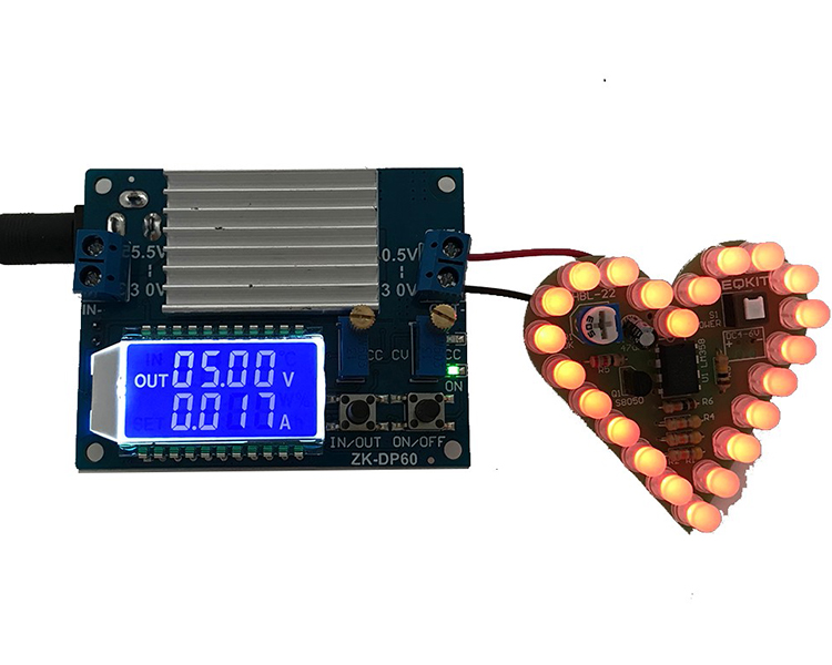
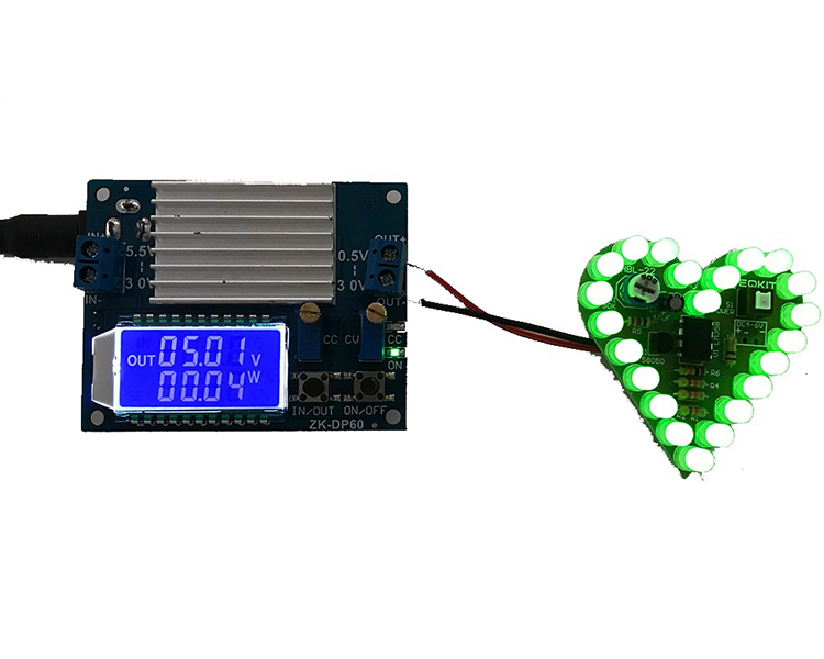
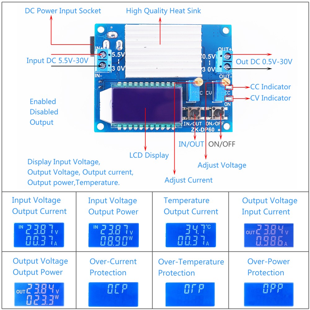
ZK-DP60 is a DC adjustable constant voltage constant current step down/up power supply module with LCD display.HD display input voltage and output voltage, current, power and display status.Adjustable stable output voltage and current.Set output current to meet the demand.It can be used as ordinary buck power supply module, charger and LED constant current driver.Simple and efficient, practical.
2.Features:
1>.High voltage resistant terminal.
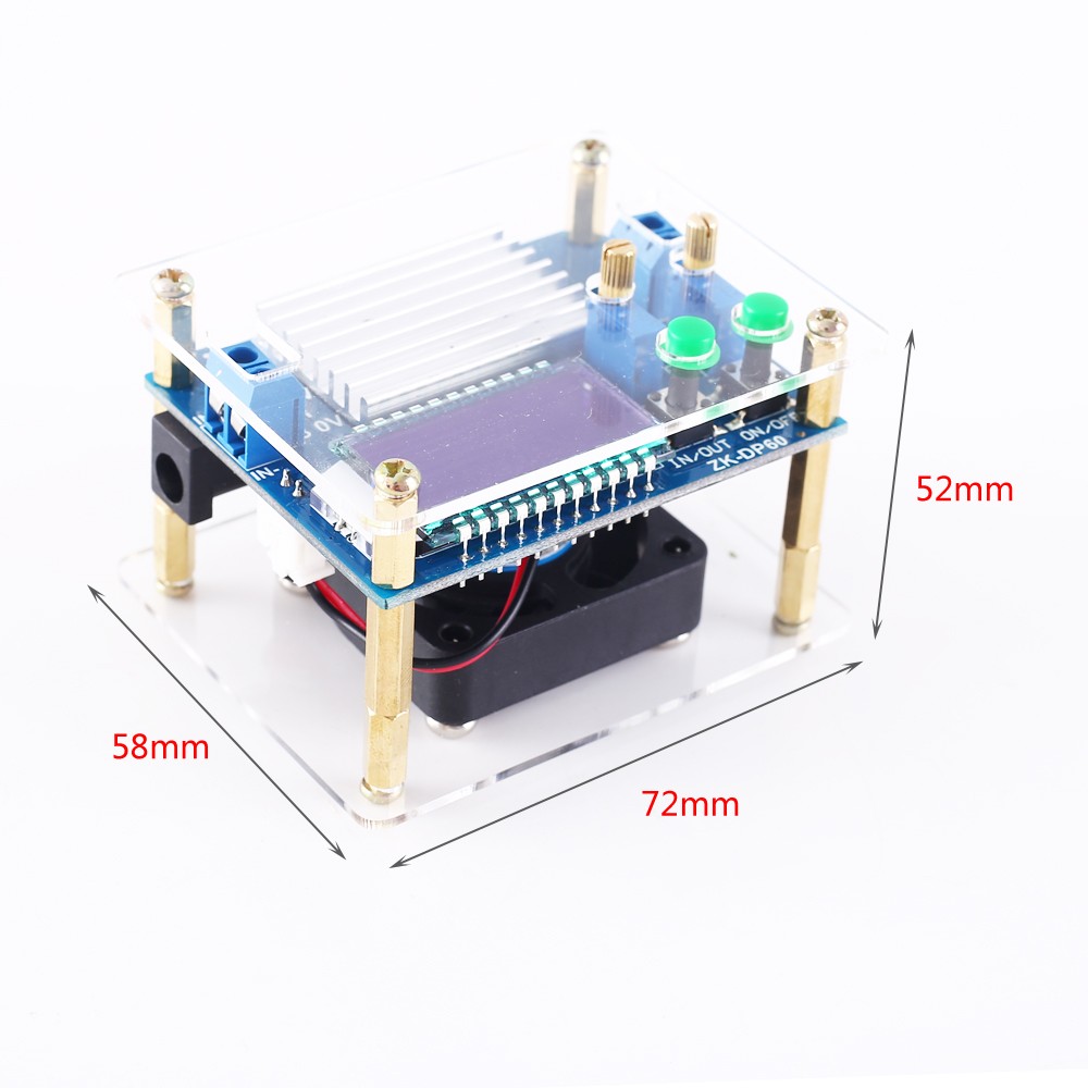
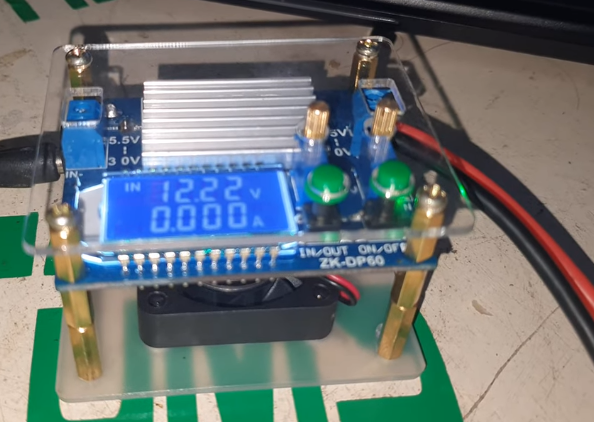
2>.With high quality acrylic shell.
3>.Support enabled/disabled output.
4>.Support anti-reverse protection.
5>.Support anti-backflow Protection.
6>.Support short circuit protection.
7>.Support over-current protection.
8>.Support over-power protection.
9>.Support over-temperature protection.
10>.Support Automatic buck/boost voltage.
11>.LCD screen HD display.
12>.Support charging function.
13>.Support display input voltage.
14>.Support display output voltage, current, power.
15>.Support working status indicator.
16>.Multiple parameters are displayed simultaneous.
17>.High current, low heat.
18>.Powerful cooling fan.
3.Parameters:
1>.Product Name:ZK-DP60 60W 6A Step Down/Up Power Supply Module
2>.Product Number:ZK-DP60
3>.Working Voltage:DC 5.5V-30V
4>.Output Voltage:DC 0.5V-30V
5>.Output Current:6A
6>.Output Power:60W
7>.Voltage Display Range:0~30V
8>.Voltage Display Precision:1%
9>.Voltage Display Resolution:0.01V
10>.Current Display Range:0~6A
11>.Current Display Precision:1%
12>.Voltage Display Resolution:0.001A
13>.Conversion efficiency:About 88%
14>.Working current:30mA
15>.Soft Starter:Yes(Failure at high power load)
16>.Anti-reverse Protection:Yes
17>.Anti-backflow Protection:Yes
18>.Short Circuit Protection:Yes
19>.Work frequency:180KHz
20>.Over-temperature Protection:100℃
21>.Over-current Protection:6A
22>.Over-power Protection:60W
23>.Fan working condition:>3A or >20W or >40℃
24>.Working Temperature range:-20℃~100℃
25>.Working Humidity range:0%-95%RH
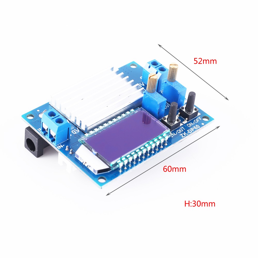
26>.Size:66*52*30mm
4.Button/Potentiometer/LED introduction:
1>.Long press means need keep press for more than 3second.
2>.ON/OFF:Short Press to select enabled/disabled output.Long press is used to set default enabled/disabled output when power-ON.
3>.IN/OUT:Short Press to switch display input voltage or output voltage or temperature.Long press is used to switch display output current or output power.
4>.CV Potentiometer:Adjust output voltage.Increase the output voltage when rotating clockwise.
5>.CC Potentiometer:Adjust output current.Increase the output current when rotating clockwise.
6>.ON LED:Green LED.Output indicator.It will turn ON when there is a output at output terminal.
7>.CC LED:Red LED.Constant current output indicator.It enters the constant current state when the load current reaches the set current and CC constant current indicator turns ON.
5.Using Steps:
1>.As a ordinary step down power module:
1.1>.Connect right input voltage at input terminal;
1.2>.Adjust CV constant voltage potentiometer to set output voltage according to require.
1.3>.Rotate CC potentiometer counterclockwise more than 10 turns at first.
1.4>.Short circuit between OUT+ and OUT-(Connect both by wire).Or test Output short circuit current by multimeter at 10A or 20A(Connect two Test Probes to output terminal on module).
1.5>.Rotate CC constant current potentiometer clockwise to set output current according to require over-current protection value.
1.6>.Test and using(E.g:Module’s maximum output current is 2A if display 2A on multimeter.Red LED indicator will turn on if output reach to 2A.Otherwise LED is OFF.)
1.7>.The output voltage will decrease due to the current sampling resistor at the output. The higher the current, the more the voltage is reduced.
2>.As a charger:
2.1>.Tops:Power module can not be used as charger module if it does not support constant current function.The voltage difference between the battery with insufficient voltage and the charger is very large.Causes excessive charging current even damage the battery.So it need keep charging in constant current mode to reaching a certain level.Then automatically switch back to constant voltage charging.
2.2>.Make sure floating charge voltage and charge current for battery.If the lithium battery’s parameter is 3.7V/2200mAh, then the float charge voltage is 4.2V, and the maximum charging current is 1C, which is 2200mA.
2.3>.Connect right input voltage at input terminal.(Note:Please don’t connect load during set parameter).
2.4>.Test output voltage by multimeter and adjust CC potentiometer to make sure output voltage reach to require floating charge voltage.(If charge a 3.7V lithium battery, adjust the output voltage to 4.2V)
2.5>.Rotate CC potentiometer counterclockwise more than 10 turns at first.
2.6>.Short circuit between OUT+ and OUT-(Connect both by wire).Or test Output short circuit current by multimeter at 10A or 20A(Connect two Test Probes to output terminal on module)
2.7>.Rotate CC constant current potentiometer clockwise to set output current according to require charge current value.
2.8>.Connect battery at output terminal and start to charging.
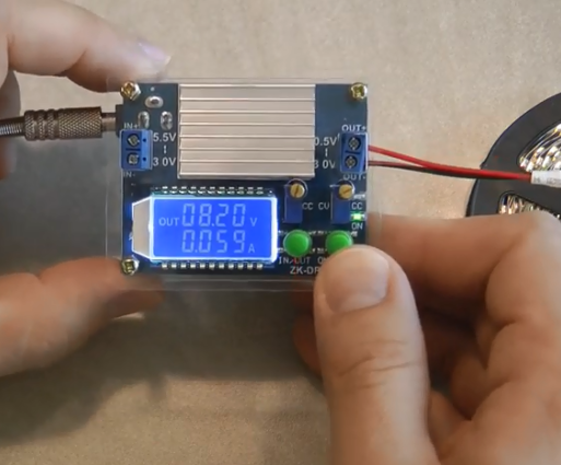
3>.As a high power LED constant current driver:
3.1>.Make sure LED working current and maximum working voltage.
3.2>.Connect right input voltage at input terminal.(Note:Please don’t connect load during set parameter).
3.3>.Test output voltage by multimeter at output terminal and adjust CV potentiometer to set output voltage to LED’s maximum working voltage.
3.4>.Rotate CC potentiometer counterclockwise more than 10 turns.
3.5>.Short circuit between OUT+ and OUT-(Connect both by wire).Or test Output short circuit current by multimeter at 10A or 20A(Connect two Test Probes to output terminal on module)
3.6>.Rotate CC constant current potentiometer clockwise to set output current according to require LED working current.
3.7>.Connect LED and test.
6.Note:
1>.Input undervoltage protection voltage is 4.7V.Module need re-power if input less than 4.7V.
2>.Please rotate the CV potentiometer counterclockwise more than 20 turns if there is no output voltage.
3>.It is a DC power module,So it can not connect to AC power.
4>.Module need re-power after short circuit protection.
5>.Please connect input before connect battery when use as charge and make sure output voltage is higher than battery voltage.
6>.’IN-’ and ‘OUT-’ can not be connect together,otherwise module can not support constant current output.
7>.Please make sure input power is more than load power.
8>.Please step down output power if module is hot.
9>.Please read use manual and description before use.
7.Application:
1>.Ordinary power supply;
2>.Battery charger;
3>.LED drive power;
4>.Instrument voltage display;
5>.Test meter;
6>.Circuit test;
7>.Power conversion.
8.Package:
1>.1pcs ZK-DP60 60W 6A Step Down/Up Power Supply Module;
2>.1pcs Heat Sink;
3>.1pcs Fan;
4>.2pcs Acrylic shell;
5>.8pcs M3*11+6mm Copper column;
6>.4pcs M3*16mm Hollow Copper column;
7>.8pcs M3*6 Screw;
8>.4pcs Self-tapping screws;
9>.2pcs Button cap.
1. Tested by ICStation's Outstanding Partner Csongor Varga:
Learn More Details in the Video:
(The language in the video is English)
(The language in the video is English)
2. Tested by ICStation's Outstanding Partner One Up The Sleeve Customs:
Learn More Details in the Video:
(The language in the video is English)
(The language in the video is English)


