
- prev
- next
DIY Kit NE555 8-Channel Digital Responder CD4511 8Bit Answering Board for Soldering Practice
Product Details
1.Description:
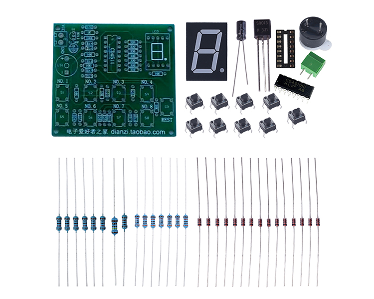
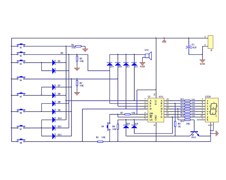
This is an 8-way answering kit with 9 keys, 8 answering numbers, and 1 answering reset. After powering on, the nixie tube displays 0 to start answering. Which of the 8 keys was pressed first, the nixie tube immediately displays the number of the first pressed key, and locks the display to indicate that the answering was successful. Pressing the other keys again has failed. Only by pressing the reset button and clearing the nixie tube 0 can a new round of answering be conducted, Press the key and the buzzer will sound.
2.Parameter:
1>.Work Voltage:DC 4.5V-5V
2>.Key function: S1-S8 is the Answer key, and S9 is the Reset key
3>.Work Temperature:-25℃~85℃
4>.Work Humidity:5%~95%RH
5>.Size:67*61mm
3.Common problem:
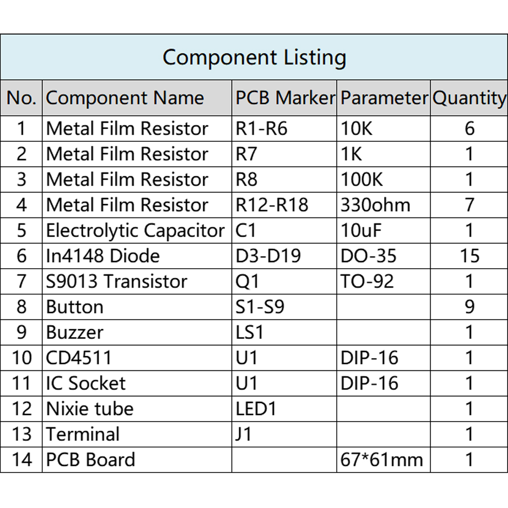
1>.Pay attention to distinguishing resistance values for welding, and the resistance values should correspond to those on the board one by one.
2>.Note that the diode 1N4148 distinguishes between positive and negative electrodes, with the black side corresponding to the side with the horizontal bar on the board, that is, the negative electrode.
3>.The long pin of the electrolytic capacitor is the positive electrode, and the buzzer is also the positive electrode of the long pin.
4>.The chip notch direction and the base notch direction should be consistent with the notch direction marked on the board.
5>.Pay attention to the direction of the nixie tube, with the decimal point below.
6>.Pay attention to the positive and negative electrodes for power supply. VCC is connected to the positive electrode, GND is connected to the negative electrode, and the DC voltage is 4.5-5.5V.
7>.Pay attention to checking for welding short circuits and faulty soldering.


