
- prev
- next
DIY Kit FM Radio Module, DC 3V Adjustable Frequency FM Digital Radio, LCD Display Wireless Receiver with 0.5W 8ohm Speaker
| Quantity | 5+ | 10+ | 30+ |
| Price | $10.99 | $10.80 | $10.35 |
Product Details
1.Introduction:
DIY Kit about FM Radio Module Adjustable Wireless Receiver with LCD Display DC 3.7V 0.5W 8ohm Speaker.
It can receiving FM station, display time, set alarm clock (the alarm is FM audio).
User can also set receiving frequency as universal frequency 87MHz ~ 108.6MHz or campus broadcast frequency 72MHz ~ 92MHz or aviation frequency 110MHz ~ 130MHz.
2.Feature:
1>.Universal frequency 87MHz ~ 108.6MHz
2>.Campus broadcast frequency 72MHz ~ 92MHz
3>.Aviation frequency 110MHz ~ 130MHz
4>.FM Alarm clock timing play function
5>.Adjustable FM stations and volume
6>.HD LCD display
3.Parameter:
1>.Item name: FM Radio Module LCD Display DIY Kit
2>.Work Voltage:DC 3V
3>.Amplifier Power:0.5W
4>.Work Temperature:-40℃~85℃
5>.Work Humidity:0%~95%RH
6>.Size(Installed):120*75*25mm
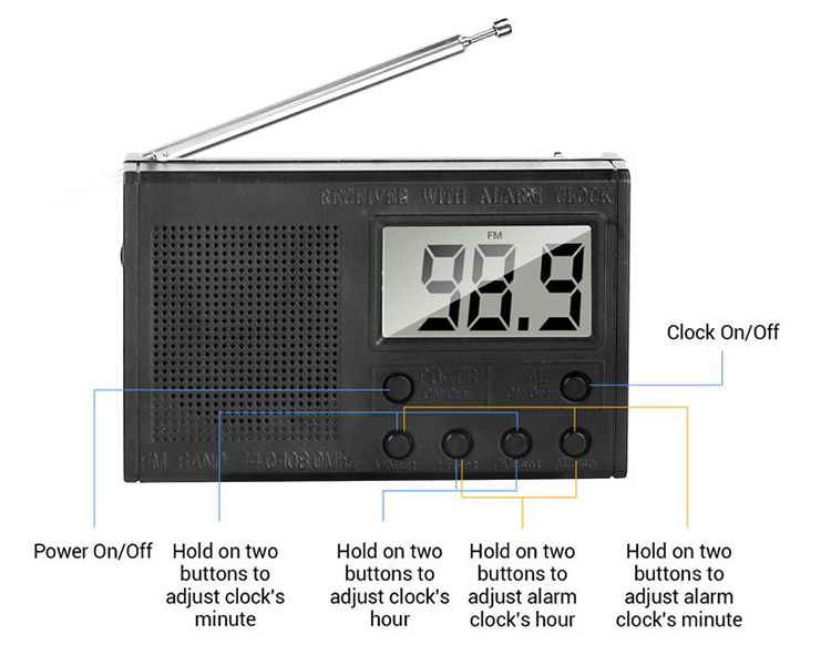
4.Button Description:
1>.POWER ON/OFF : It is used to switch FM and Time.
2>.AL ON/OFF : It is used to turn ON or OFF alarm function. It turns on the alarm function if there is a wireless symbol on LCD screen at the first line.
3>.MINset : It is used to change value for minutes. It supports press once or keep press. Note: Its value can only increase, not decrease.The minutes value reaches the maximum value(59) and then increases form 0 again. Pay attention to AM and PM on LCD screen at the first line.
4>.HEset : It is used to change value for hours. It supports press once or keep press. Note: Its value can only increase, not decrease.The hours value reaches the maximum value(12) and then increases form 0 again.Pay attention to AM and PM on LCD screen at the first line.
5>.TIMEset : It is used to enter set time mode. It is recommended to press and hold this button first and then press ‘HEset’ and ‘MINset’ to calibrate the RTC time.
6>.ALdisp : It is used to enter set alarm mode. It is recommended to press and hold this button first and then press ‘HEset’ and ‘MINset’ to set alarm time. It will display alarm time by press ‘ALdisp’ at any time.
5.Parameters:
1>.Calibrate display time:
1.1>.Make sure the screen displaying time by press ‘POWER ON/OFF’ button.
1.2>.Press ‘TIMEset’ button and keep press.
1.3>.Press or keep press ‘HEset ’ button to change hour value.
1.4>.Press or keep press ‘MINset ’ button to change minute value.
2>.Set alarm time:
2.1>.Press ‘AL ON/OFF’ button to turn ON alarm function.
2.2>.Press ‘ALdisp’ button and keep press.There is a bell symbol in the upper right corner.
2.3>.Press or keep press ‘HEset ’ button to change hour value.
2.4>.Press or keep press ‘MINset ’ button to change minute value.
2.5>.It will display alarm time by press ‘ALdisp’ at any time.
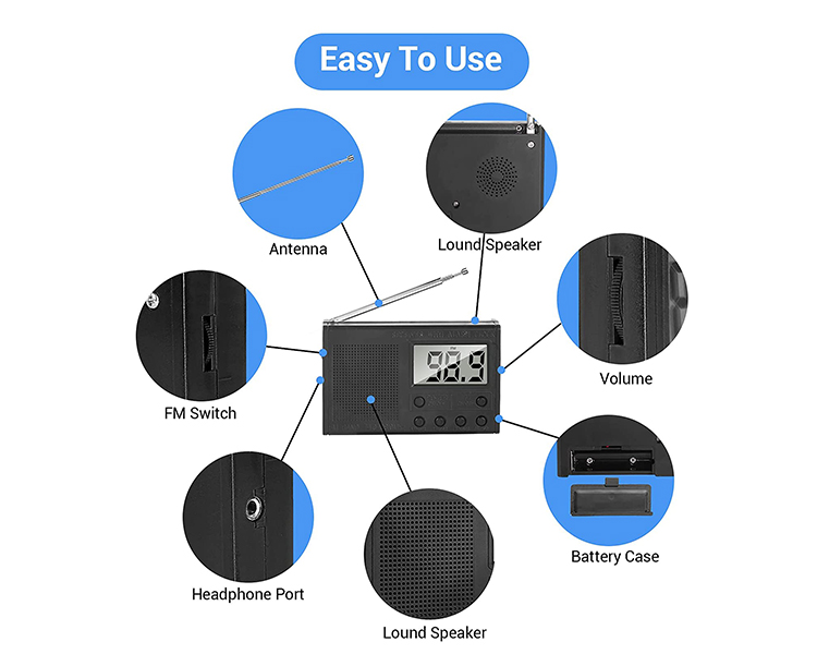
3>.Select the gear on the right to switch the FM station.
4>.Select the gear on the left to change the volume.
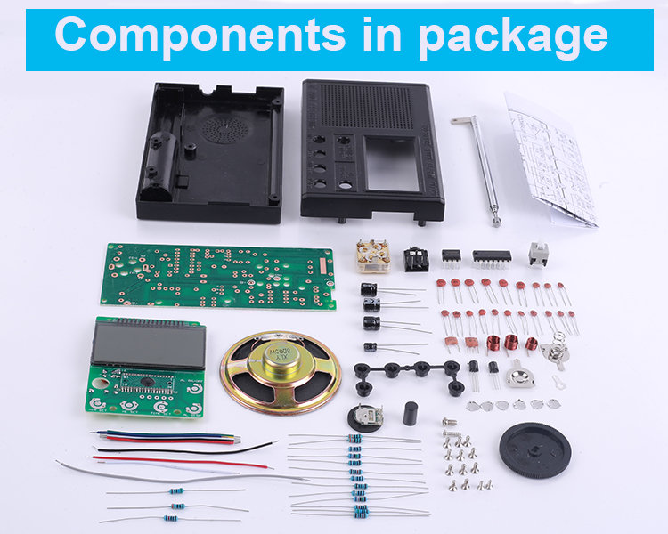
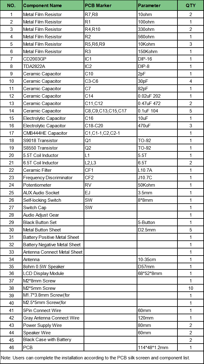
6.Components list:
7.Note:
1>.It is a DIY kit so that need finish install by user.
2>.It supports alarm clock but its alarm to play FM audio.
3>.Its receiving frequency range needs to be adjusted during installation.
4>.Its LCD will keep the display frequency or time,but can not be turn OFF.
5>.User needs to re-calibrate the time after the next battery installation.
8.Application:
1>.Training welding skills
2>.Student school
3>.DIY production
4>.Project Design
5>.Electronic competition
6>.Gift giving
7>.Crafts collection
8>.Home decoration
9>.Souvenir collection
10>.Graduation design
11>.Holiday gifts
9.Installation Tips:
1>.User needs to prepare the soldering tool at first.
2>.Please be patient until the installation is complete.
3>.The package is DIY kit.It need finish install by user.
4>.The soldering iron can't touch the components for a long time(1.0 second), otherwise it will damage the components.
5>.Pay attention to the positive and negative of the components.
6>.Strictly prohibit short circuit.
7>.Install complex components preferentially.
8>.Make sure all components are in right direction and right place.
9>.Please wear anti-static gloves or anti-static wristbands when installing electronic components.
10.Installation Steps:
Step 1: Install 2pcs 10ohm Metal Film Resistor at R7,R8. Identify the resistor value as shown in color: Brown/Black/Black/Golden/Brown.
Step 2: Install 1pcs 100ohm Metal Film Resistor at R1. Identify the resistor value as shown in color: Brown/Black/Black/Black/Brown.
Step 3: Install 2pcs 330ohm Metal Film Resistor at R4,R10. Identify the resistor value as shown in color: Brown/Brown/Black/Black/Brown.
Step 4: Install 1pcs 560ohm Metal Film Resistor at R2. Identify the resistor value as shown in color: Green/Blue/Black/Black/Brown.
Step 5: Install 3pcs 10Kohm Metal Film Resistor at R5,R6,R9. Identify the resistor value as shown in color: Brown/Black/Black/Red/Brown.
Step 6: Install 1pcs 150Kohm Metal Film Resistor at R1. Identify the resistor value as shown in color: Brown/Green/Black/Orange/Brown.
Step 7: Install 1pcs 2pF Ceramic Capacitor at C10.Pay attention to the screen printing on the surface of capacitor.
Step 8: Install 4pcs 30pF Ceramic Capacitor at C3-C6.Pay attention to the screen printing on the surface of capacitor.
Step 9: Install 1pcs 82pF Ceramic Capacitor at C7.Pay attention to the screen printing on the surface of capacitor.
Step 10: Install 1pcs 0.02uF 202 Ceramic Capacitor at C14.Pay attention to the screen printing on the surface of capacitor.
......
Please Click Here to download the complete installation manual:
.png)


