
- prev
- next
Simple Flash Circuit LED Light Electronic Soldering Practice Kits for Beginner
$1.39$1.9930%
00d : 00h : 00m : 00s
Item ID: 1895
Product Details
Description
Kits type: YSG - 1
Working voltage: 3-9 v
LED colors: red highlight
PCB size: 31 * 28 mm
Module Diagram
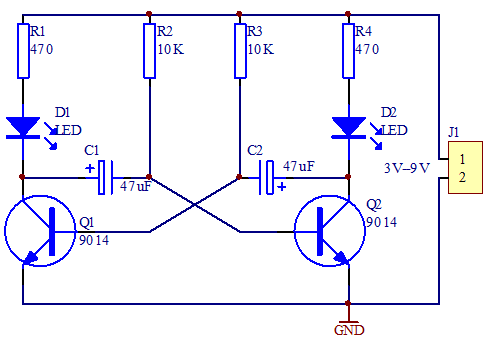
Principle of Operating
For YSG-1, the Q1 and Q2 form the multivibrator which used to control the flashing of these two LEDs.
And here is the operating principle of multivibrator. As there is difference between the components, Q1 or Q2 will be turn on at the first place after the boot.
If Q1 turns on at the first place, the voltage of Q1 collector will be 0V and the D1 starts light. As it cannot have a sudden change on the voltage of two ends of the capacitance, the Q1 collector with 0V will let the base potential of Q2 reduced to 0V through C1 and let the Q2 turn off.
D2 turns off at this time. When the charge voltage of C1 increases to the breakover voltage of Q2, the Q2 turns on. And the voltage of Q2 collector reduced to 0V and D2 starts to light. In the same way, the Q2 collector with 0V will let the base potential of Q1 reduced to 0V through C2 and let the Q1 turn off. D1 turns off at this time.
The multivibrator will operate according to this cycle to let two LEDs light by turns.
And the flashing frequency of these two LEDs depends on the specification of C1、C2、R2 and R3.
Enjoy Video from icstation team:


