
- prev
- next
DC 4-6V DIY FM Transmitter Wireless Microphone FM Frequency Modulation MP3 Transponder DIY Kits
Product Details
DIY FM Stereo Transmitter Wireless Radio
Parameter:
| NO. | Parameter | Value |
| 1 | Name | FM stereo transmitter |
| 2 | Model | RF-03PLL |
| 3 | Operating Voltage | DC 4-6V |
| 4 | Operating Current | 20-40mA |
| 5 | Transmitting Distance | 20-80M (no barrier) |
| 6 | Transmitting Frequency | 87-108MHz (Change frequency by toggle Switches) |
| 7 | Power Indication | YES; when lower than 4V, LED off automatically |
| 8 | Oscillation mode | PLL Phase-locked loop |
| 9 | Frequency Stability | Zero drift |
| 10 | Sound Quality | Good; Stereo dual channel transmitting, Auto gain control |
| 11 | Microphone | YES, onboard the PCB |
| 12 | Microphone Using Distance | 1M |
| 13 | Microphone And Audio Input Switch Way | unplug the audio wire, the microphone will operate normally |
Application:
Private radio
Car audio transmitter
Wired audio to wireless
Coding Table:
| Low frequency | D0 | D1 | D2 | D3 | Frequency |
| S3->L88M | L | L | L | L | 87.7MHz |
| H | L | L | L | 87.9MHz | |
| L | H | L | L | 88.1MHz | |
| H | H | L | L | 88.3MHz | |
| L | L | H | L | 88.5MHz | |
| H | L | H | L | 88.7MHz | |
| L | H | H | L | 88.9MHz | |
| High frequency | L | L | L | H | 106.7MHz |
| S3->L10M | H | L | L | H | 106.9MHz |
| L | H | L | H | 107.1MHz | |
| H | H | L | H | 107.3MHz | |
| L | L | H | H | 107.5MHz | |
| H | L | H | H | 107.7MHz | |
| L | H | H | H | 107.9MHz |
Components List:
| NO. | Component Name | PCB Marker | Parameter | QTY |
| 1 | Metal Film Resistor | R8 | 4.7R | 1 |
| 2 | Metal Film Resistor | R9,R22 | 100R | 2 |
| 3 | Metal Film Resistor | R10,R11,R14,R23,R26 | 2.2K | 5 |
| 4 | Metal Film Resistor | R21,R24 | 4.7K | 2 |
| 5 | Metal Film Resistor | R1,R3,R4,R5,R6,R7,R12,R13,R18,R19,R20,R25 | 10K | 12 |
| 6 | Metal Film Resistor | R2,R15 | 47K | 2 |
| 7 | Ceramic capacitor | C27 | 3P | 1 |
| 8 | Ceramic capacitor | C26 | 15P | 1 |
| 9 | Ceramic capacitor | C24 | 22P | 1 |
| 10 | Ceramic capacitor | C3,C6,C19,C23,C25 | 30P | 5 |
| 11 | Ceramic capacitor | C17,C22,C28 | 101P | 3 |
| 12 | Ceramic capacitor | C31,C35 | 102P | 2 |
| 13 | Ceramic capacitor | C16,C21 | 222P | 2 |
| 14 | Ceramic capacitor | C7,C33 | 103P | 2 |
| 15 | Ceramic capacitor | C2,C5,C12,C20 | 104P | 4 |
| 16 | Electrolytic capacitor | C11,C13,C14,C15,C29 | 1uF | 5 |
| 17 | Electrolytic capacitor | C18,C30 | 10uF | 2 |
| 18 | Electrolytic capacitor | C34 | 22uF | 1 |
| 19 | Electrolytic capacitor | C32 | 47uF | 1 |
| 20 | Electrolytic capacitor | C1,C4 | 470uF | 2 |
| 21 | BH1417F | IC1 | SOP-22 | 1 |
| 22 | Transistor | Q2,Q4,Q5 | S9018 | 3 |
| 23 | Transistor | Q1 | S9014 | 1 |
| 24 | Crystal | X1 | 7.6MHz | 1 |
| 25 | Toggle Switches | S1,S3 | 3P2 | 2 |
| 26 | Switch | S2 | 4-Position | 1 |
| 27 | Zener diode | ZD1 | 4.3V | 1 |
| 28 | Varactor diodes | VD1 | FV1043 | 1 |
| 29 | LED | LED1 | Red 3mm | 1 |
| 30 | Inductance | L1 | 150uH | 1 |
| 31 | Inductance | L4 | 5T | 1 |
| 32 | Inductance | L2 | 8T | 1 |
| 33 | Audio input socket | JK1 | Stereo 5 pin | 1 |
| 34 | Microphone | MIC | F10*H7mm | 1 |
| 35 | Battery terminal | J1 | KF301-2 | 1 |
| 36 | Copper wire | ANT | 300mm | 1 |
| 37 | PCB | 73*51mm | 1 |
NOTE: You can complete the installation by PCB silk screen and components list.
Download the Installation Instructions here:

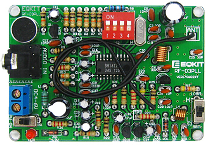
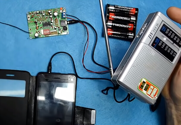
Finished Product Picture:
( Note: The black cable is antenna, should be soldered on the "ANT" place. )
I. Tested by ICStation's Outstanding Partner 12voltvids:
![]()
![]()
![]()
![]()
![]()
Learn More Details in the Video:
(The language in the video is English)
II. Tested by ICStation's Outstanding Partner LearningZone:
![]()
![]()
![]()
![]()
Learn More Details in the Video:
(The language in the video is English)
III. Tested by ICStation's Outstanding Customer mosslack:
![]()
![]()
![]()
![]()
Learn More Details in the Video:
(The language in the video is English)
IV. Tested by ICStation's Outstanding Partner ELECTROJUANYU:
Learn More Details in the Video:
(The language in the video is Spanish)
Tested by ICStation's Outstanding Partner randomtronic:
![]()
![]()
Learn More Details in the Video:
(The language in the video is English)


