- prev
- next
DC 5V 12V 24V Trigger Counter Module MOS Delay Circuit Switch Timer 32-Function
$5.99
Item ID: GY17192
Product Details
1.Description:
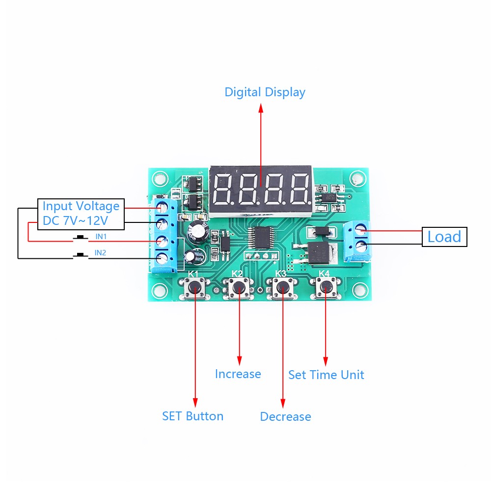
It is a delay MOS tube module.It can be used to control motors,LED strips,DC motors,miniature water pumps,solenoid valves,etc.
2.Feature:
1>.Digital dispiay
2>.No noise
3>.No sparks
4>.No electromagnetic interference
5>.long lasting
3.Parameter:
1>.Product Name:Delay MOS Tube Module
2>.Model:YF-11
3>.Input Voltage:DC 7V~24V
4>.Load Current:10A(MAX)
5>.Time Range:0.01s~999minute
6>.Operating Temperature:-20℃~85℃
7>.Operating Humidity:5%~95%RH
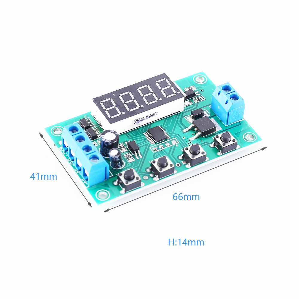
8>.Size:66*41*14mm
4.Function:
1>.P-11:Inching Mode.When signal input,the output turn ON.When signal disappears,the output turn OFF.
2>.P-12:Self-locking Mode.Input a signal,the output turn ON.Input the signal again,the output turn OFF.
3>.P-13:Input signal,the output turn ON and start delay T1.After delay,turn OFF.Invalid trigger during delay.
4>.P-14:Input signal,the output turn ON and start delay T1.After delay,turn OFF.Trigger retime during delay.
5>.P-15:Input signal,the output turn ON and start delay T1.After delay,turn OFF.Trigger overlay timing during delay.
6>.P-16:Input signal,the output turn ON and start delay T1.After delay,turn OFF.Trigger a reset during the delay.
7>.P-17:Input signal,the output turn ON.When the signal disappears,turn OFF and start delay T1.After delay,turn OFF.Input the signal again during the delay period,keep output,and stop the timing.
8>.P-18:After power-on,the output turn ON and start delay T1.After delay,the power-off.Until the next power-up.
9>.P-21:Input signal,start delay T1.After delay,the output turn ON.
10>.P-22:Input signal more than T1,the output turn ON.The signal disappear,the output turn OFF.
11>.P-23:When the signal disappears more than T1,the output turn ON.When input singal,the output turn OFF.
12>.P-24:Input signal more than T1,the output turn ON.The signal disappear more than T1,the output turn OFF.
13>.P-25:Input signal more than T1,the output turn ON.Input the signal more than T1 again,the output turn OFF.
14>.P-26:Input signal,the output turn ON and start delay T1.After delay,turn OFF.When the signal disappear,the output turn ON and start delay T1.After delay,the output turn OFF.
15>.P-27:Input the pulse signal,the output turn OFF.The pulse signal disappear more than T1,the output turn ON.(If the signal persists or disappears, it is regarded as no pulse signal.)
16>.P-28:After power-on,the output turn OFF and start delay T1.After delay,the turn ON until power-off.
17>.P-31:After power-on,the output turn OFF will start for T1,stop for T2.Infinite loop until power-off.
18>.P-32:Input signal,start P-31 infinite loop.The signal disappear,end the loop.
19>.P-33:Input a signal,start P-31 infinite loop.Input the signal again,end the loop.
20>.P-34:After power-on,the output turn OFF and start delay T1.After delay,the turn ON.After T2,ture OFF.
21>.P-35:Input signal,the output turn OFF and start delay T1.After delay,the turn ON.After T2,ture OFF.
22>.P-36:After input signal more than T1,the output turn ON and start delay T2.After delay,the turn OFF.After T2,ture OFF.When the signal disappear,timing cleared to stop.
23>.P-37:Input signal,the output turn ON and start delay T1.After delay,the turn OFF and start delay T2.Signal trigger is invalid during T3(T3=T1+T2).
24>.P-38:Input signal,the output turn ON and start delay T1.After delay,the turn OFF and start delay T2.After delay T2,the output turn OFF after turn ON T1.
25>.P-41:Input signal,the output turn OFF,the signal disappear,the output turn ON and start delay T1.After delay,the turn OFF.
26>.P-42:The signal disappear,after delay T1,the output turn ON and start delay T2.After delay,the turn OFF.
27>.P-43:The signal disappear more than T1,the output turn ON and start delay T2.After delay,the turn OFF.
28>.P-44:After power-on,the output turn ON and start delay T1.After delay,the turn OFF T2.Automatic stop for C times.
29>.P-45:After power-on,the output turn OFF,Input signal,the output turn ON and start delay T1.After delay T1,the turn OFF and start delay T2.After delay T2,the output turn OFF.Automatic stop for C times.Input the signal again,do it again.
30>.P-46:After input signal A times,the output turn ON.Until power-off turn OFF.
31>.P-47:After input signal A times,the output turn ON and start delay T2.After delay,the turn OFF.
32>.P-48:In T3,after input signal is continuously more than A times,the output turn ON and then turn OFF for T2.
5.Button Description:
1>.Display will display "----" when power on.
2>.Press K1 at the first time(more than 1s),the display "P-11",press K2 and K3 to adjust master model,press K3 and K4 to adjust function.
3>.Press K1 at the second time,the display "A001",press K2 and K3 to adjust T1,press K4 adjust decimal point.
4>.Press K1 at the third time,the display "B001",press K2 and K3 to adjust T2,press K4 adjust decimal point.
5>.Press K1 at the fourth time,display "----",the module enter standby.
6>.Press K4 in standby mode to permanently turn off/on the display and switch the low power consumption mode.
6.Decimal Point Unit Description:
1>.When display "X.XX",the timing range is 0.01s~9.99s.
2>.When display "XX.X",the timing range is 0.1s~99.9s.
3>.When display "XXX",the timing range is 1s~999s.
4>.When display "XXX.",the timing range is 1minute~999minute.