- prev
- next
Type-C Power Supply Module for MCU Controller 18650 Battery Charge Discharge 1.8V 3.3V 5V
Product Details
1.Introduction:
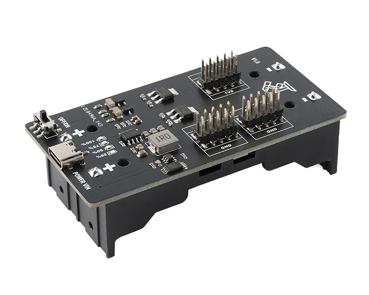
The module can be used to supply power to the microcontroller by inputting a 5V power supply through a 3.7V 18650 lithium battery and Type-C USB battery, and can also be used as a module with some suitable electrical parameters (not directly connected to the motor).
The module outputs three different voltages of 5V, 3.3V and 1.8V in the form of 2.54mm distance pins, which can be used as power supply in a variety of scenarios. The module is equipped with 4 indicator lights to distinguish the current battery level and battery charging status.
2.Feature:
1>.The indicator identifies the current charge level and battery charge.
2>.Punch and put at the same time.
3>.Flush and discharge.
3.Parameter:
1>.USB port input voltage: 4.7~5V
2>.Battery working voltage: 3.1~4.3V
3>.Full battery voltage: 4.15~4.25V
4>.MAX Output Current: 5V: 1.5A; 3.3V: 400mA; 1.8V: 150mA
5>.Cut-off output voltage: 3V for battery
6>.Flush and discharge: The output voltage is 4.5V MAX 400mA left and right
7>.Work Temperature:-25℃~85℃
8>.Work Humidity:0%~95%RH
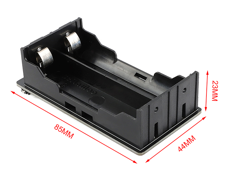
9>.Size: 85*44*23MM
4.LED Indicator Description:
1>. Discharge Mode:
LED1 : Power Remaining ≤ 25% (when flashing, it means that the power is less than 3% and it is time to charge)
LED2 : Power Remaining ≤ 50 %
LED3 : Power Remaining ≤ 75 %
LED4 : Power Remaining ≤ 100%
2>. Charging Mode:
LED1 : Flashing indicates current charge<25%
LED2 : Flashing indicates current charge<50%
LED3 : Flashing indicates current charge<75%
LED4 : Flashing indicates that the current charging power is < 100%, and it is always on to be full
5.Note:
1>.There is a toggle switch on the module to control the output, when dialed to the left is to close the output, to the right to open the output.
2>.If the battery protection chip is activated for protection, a new battery is installed, and the on/off indicator is turned on, it can be connected to the USB port to charge and activate.
3>.After the switch is turned off, the indicator light will remain on for 30 seconds and then turn off.
4>.The cells connected to the modules are connected in parallel, and the batteries should not be connected in series.
5>.Distinguish between positive and negative electrodes, and the reverse will burn out the module (there are positive and negative screen prints on the board, and the battery should be installed strictly according to the screen print instructions).
6>.The output should not be short-circuited into the output interface.
The module output port cannot be directly connected to the motor.
6.Package:
1pcs Type-C MCU power module.