
- prev
- next
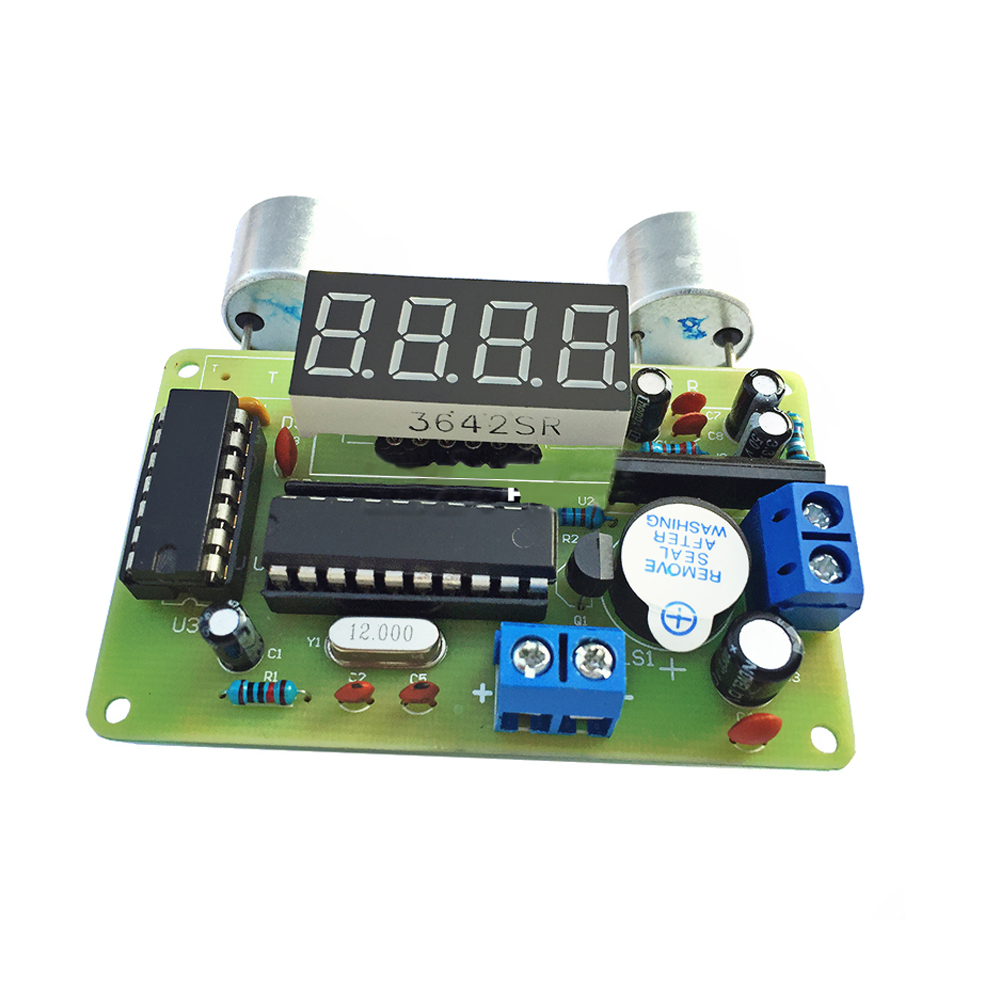
DIY Kit Ultrasonic Range Finder Distance Measuring Transducer Sensor Electronic Kits for Soldering Learning
$8.59
| Quantity | 10+ | 30+ | 50+ |
| Price | $5.50 | $5.20 | $4.80 |
Item ID: 13605
Product Details
Supply voltage: DC 4.5-6V
Detection range: 25-400cm (indoor)
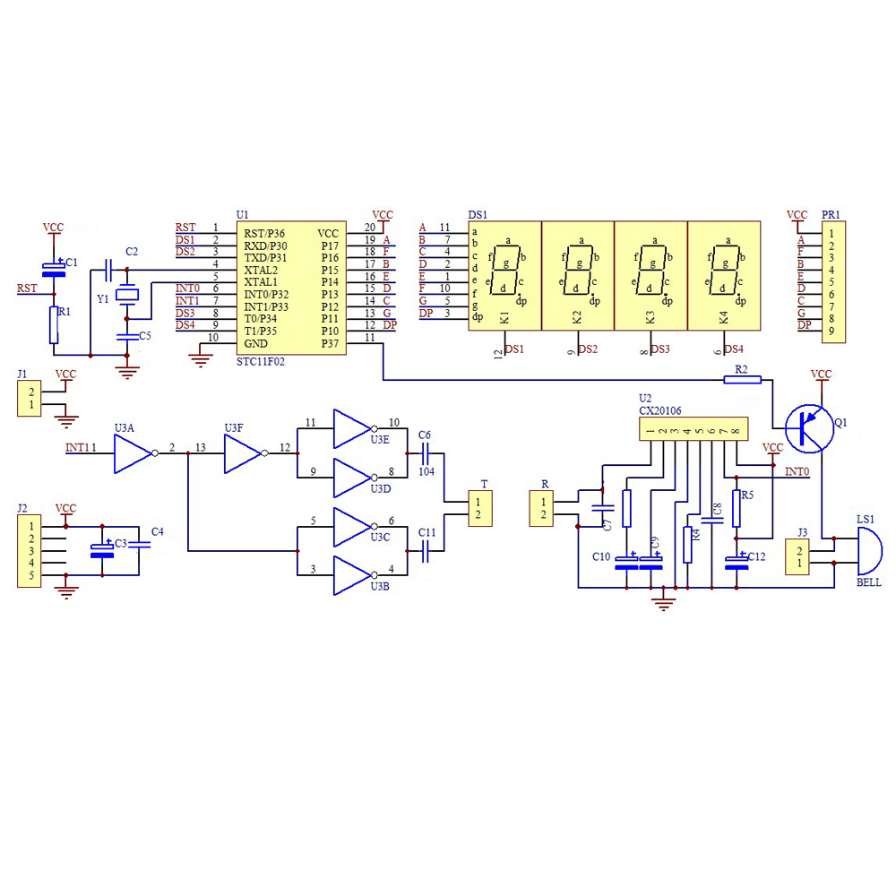
▲Using ultrasonic waves to measure obstacle distance, the ultrasonic range finder sends a 40KHz ultrasonic pulse through the ultrasonic transmitter.
And receives the transmitted echo with the ultrasonic receiver.
▲By measuring the time interval between transmission and reception, the distance can be measured by conversion.
▲The 4-digit digital tube displays the distance in meters to millimeters.
Since the PCB board can also transmit ultrasonic waves, the ultrasonic distance measuring kit has a distance.
▲Generally, the ultrasonic reflection signal and the transmitting head can not be transmitted to and received through the PCB within 25CM.
▲The buzzer is used to indicate the distance of the distance.
▲The farther the distance is, the longer the buzzer interval is.
The shorter the buzzer interval is, the more the car is reversed.
Note:
1.The ultrasonic transmitting head and the receiving head are distinguished according to the characters on the back side.
2.The mounting head marked with T on the circuit board, the receiving head labeled R, the transmitting head and the receiving head are parallel to each other, and the head is aligned.
3.Do not shorten the header of the transmitter and receiver, and solder the pins directly to the back of the board.

Tested by ICStation's Outstanding Partner bzoli5706:
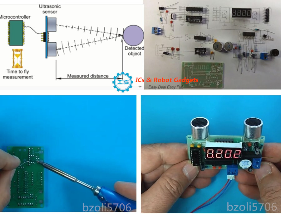
Learn More Details in the Video:
(The language in the video is English)
(The language in the video is English)
Tested by ICStation's Outstanding Partner Stefano91ste:
Learn More Details in the Video:
(The language in the video is English)
(The language in the video is English)


