
- prev
- next
White Noise Signal Generator DIY Kit DC 12V Electronic Kit 2-Channel Output
| Quantity | 10+ | 30+ | 50+ |
| Price | $1.25 | $1.10 | $0.99 |
Product Details
Description:
This is a DIY white noise signal generator kit. You need to solder it by yourself.
Parameters:
1>. Power supply DC 12V.
2>. Two way signal output:
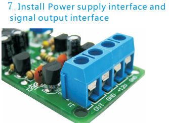
J1 output 1V fixed non adjustable noise signal, and the internal resistance is big. It is suitable for the front stage PRE input.
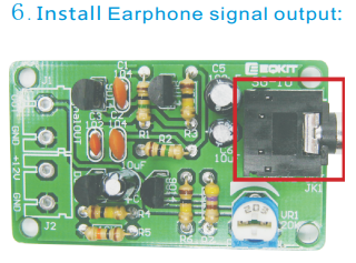
JK1 output 1V continuous adjustable white noise signal, and the internal resistance is small. It can directly drive headphones.
P.S. Two signals will not interact with each other.
Application:
White noise signal, commonly known as noise, is similar to the bottom noise of the radio. It can be used in burn-in, test, therapy on insomnia and so on!
Component list:
| NO. | Component Name | PCB Marker | Parameter | Quantity |
| 1 | Metal Film Resistor | R7 | 470ohm | 1 |
| 2 | Metal Film Resistor | R5 | 10K | 1 |
| 3 | Metal Film Resistor | R3,R4,R6 | 100K | 3 |
| 4 | Metal Film Resistor | R1,R2 | 1M | 2 |
| 5 | Ceramic capacitor | C3 | 0.001uf | 1 |
| 6 | Ceramic capacitor | C1,C2 | 0.1uf | 2 |
| 7 | Electrolytic capacitor | C4,C6 | 10uf | 2 |
| 8 | Electrolytic capacitor | C5 | 100uf | 1 |
| 9 | Potentiometer | VR1 | 20K | 1 |
| 10 | S9014 | Q1-Q4 | TO-92 | 4 |
| 11 | Connector | J1,R2 | KF301-2 | 2 |
| 12 | Audio socket | JK1 | 5P-Stereo | 1 |
| 13 | PCB | 1 |
Install tools:
YOU MAY NEED PREPARE THE FOLLOWING TOOLS TO INSTALL THE KITs
| Electric soldering iron | Multimeter | Solder wire |
| Soldering iron holder | Diagonal cutting pliers | Screwdriver |
| Tweezers | Sharp-nose pliers | Solder sucker |
| Sponge | Screwdriver kit |
Installation Steps:
1.Install RES: R1.R2=1MΩ.R3.R4.R6=100KΩ. R5=10KΩ.R7=470Ω
.png)
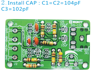
2.Install CAP:C1=C2=104pF C3=102pF
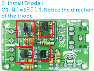
3.Install Triode: Q1-Q4=S9014.Notice the direction of the triode
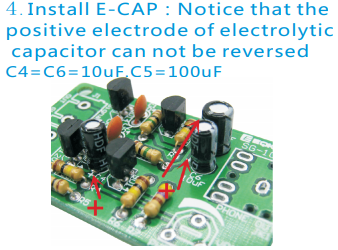
4.Install E-CAP:Notice that the positive electrode of electrolytic capacitor can not be reversed C4=C6=10uF.C5=100uF
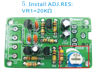
5.Install ADJ.RES: VR1=20KΩ
6.Install Earphone signal output:
7.Install Power supply interface and signal output interface
8.Instructions: Noise signals are similar to radio noise Very widely used. The machine is powered by DC 12V Two way signal output: J1 Output 1V fixed non adjustable noise signal Suitable for front stage pre input JK1 Output 1V continuously adjustable noise signal It can drive headphones directly Two signals do not affect each other
Download the Installation Manual Here:
.png)
Download Link:
http://attach01.oss-us-west-1.aliyuncs.com/IC/DIY-Manual/12589.pdf
Tested by ICStation's Outstanding Partner bzoli5706:
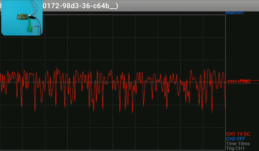
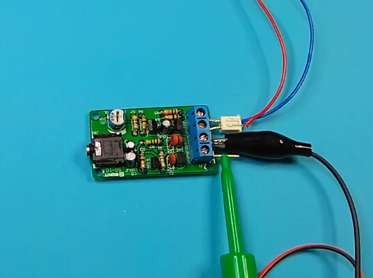
Learn More Details in the Video:


