
- prev
- next
Red Yellow LED Flashing Light Electronic Kits Soldering Practice Board for Students School Soldering Practice
| Quantity | 5+ | 10+ | 30+ | 50+ |
| Price | $4.00 | $3.90 | $3.70 | $3.50 |
Product Details
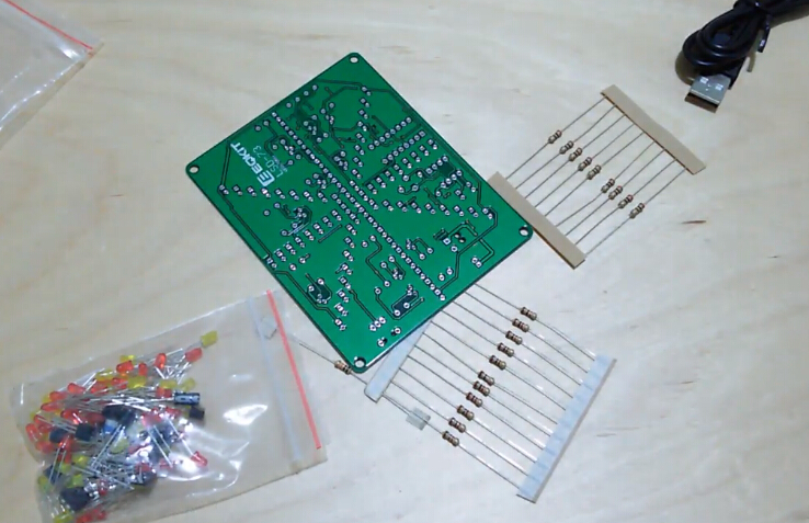
Description:
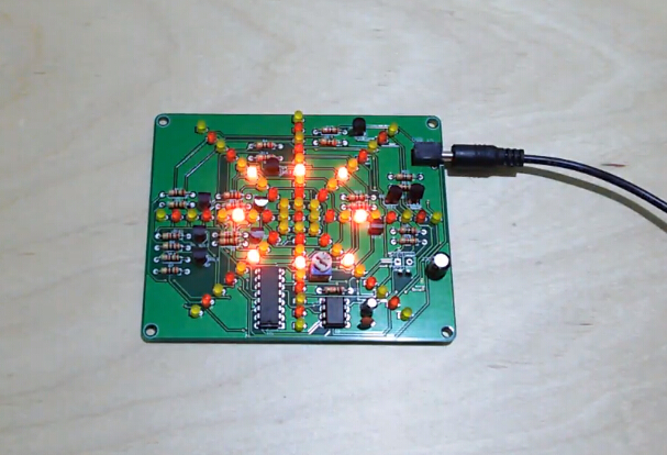
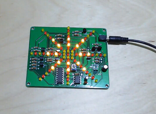
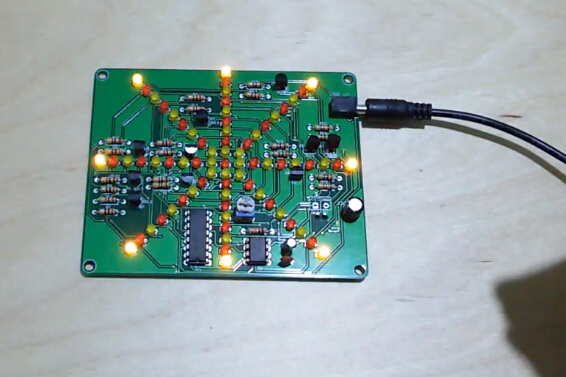
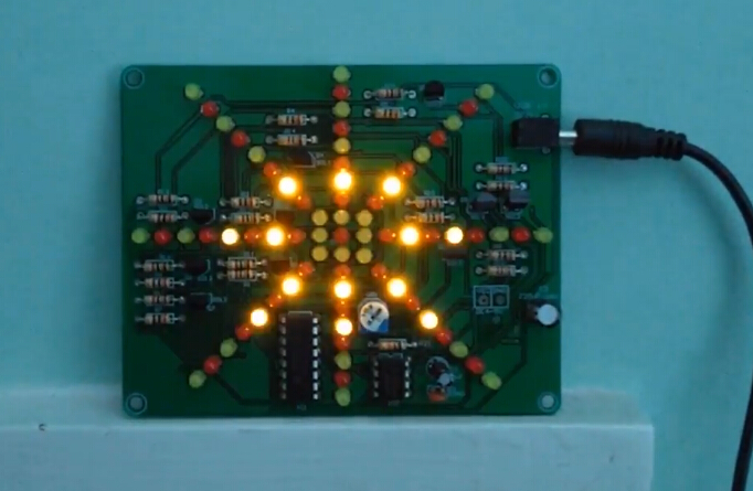
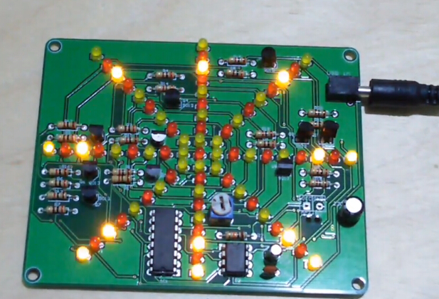
★The LED light flows from the inside to the outside, creating the effect of the exploding water lamp.The speed of LED flow can be adjusted to meet various demands.
★High quality PCB, even beginners can easily weld successfully. It has clearly marked the electronics components, even beginners can easily solder successfully.
★Complete user manual, which will guide you how to install step by step, perfect for school basic electronics experiment projects.
★Left to right, red, yellow, red, yellow in order to install LED.The LED's anode corresponds to the square pad.
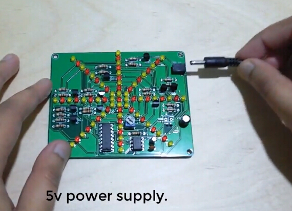
★Operating Voltage: DC 4.5-6V
★PCB size: 100*80mm
(Please noted: the PCB board color is Green as below.
Adam spayed it to Black color and done this video. Another kit appeared in the video is Dual-Color Flashing Light Analog Traffic Signal Indicator)
.jpg)
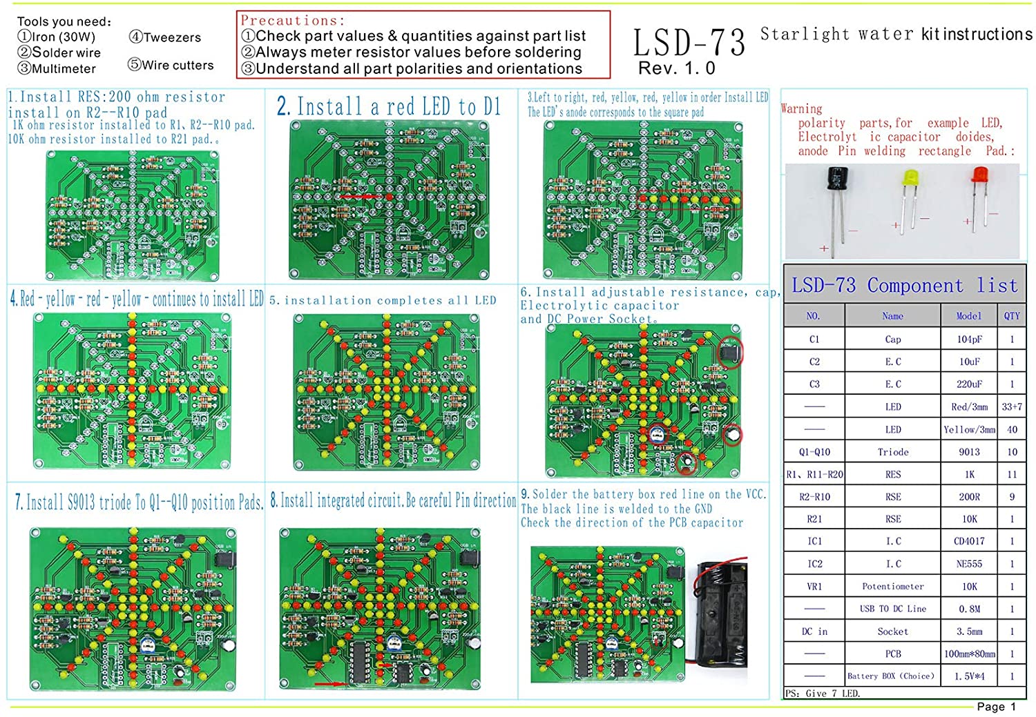
Installation Steps:
1.Install RES: 200 ohm resistor install on R2-R10 pad, 1K ohm resistor installed to R1, R2-R10 pad. 10K ohm resistor installed to R21 pad
2.Install a red LED to D1
3.Left to right, red, yellow, red, yellow in order to install LED. The LED's anode corresponds to the square pad
4.Red-yellow-red-yellow continues to install LED
5.Install all LEDs completely
6.Install adjustable resistance cap, electrolytic capacitor and DC power socket
7.Install S9013 triode to Q1-Q10 position pads
8.Install integrated circuit. Be careful of the pin direction
9.Solder the battery box red line on the VCC. The black line is weldered to the GND. Check the direction of the PCB capacitor.
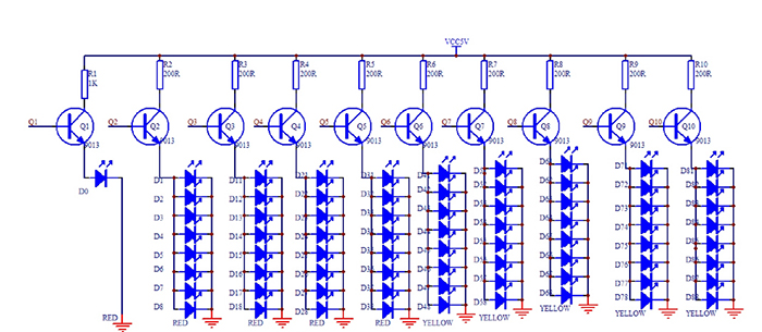
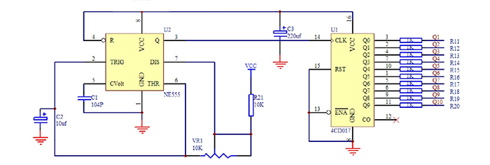
Circuit Diagram:
Component List:
| NO. | Components Name | Silk Screen | Parameter | QTY |
| 1 | Cap | C1 | 104pF | 1 |
| 2 | Electrolytic Capacitor | C2 | 10uF | 1 |
| 3 | Electrolytic Capacitor | C3 | 220uF | 1 |
| 4 | LED | Red/3mm | 33+7 | |
| 5 | LED | Yellow/3mm | 40 | |
| 6 | Triode | Q1-Q10 | 9013 | 10 |
| 7 | Resistor | R1,R11-R20 | 1K ohm | 11 |
| 8 | Resistor | R2-R10 | 200 ohm | 9 |
| 9 | Resistor | R21 | 10K ohm | 1 |
| 10 | Integrated Circuit | IC1 | CD4017 | 1 |
| 11 | Integrated Circuit | IC2 | NE555 | 1 |
| 12 | Potentiometer | VR1 | 10K ohm | 1 |
| 13 | USB to DC Line | 0.8M | 1 | |
| 14 | Socket | DC in | 3.5mm | 1 |
| 15 | PCB | 100*80mm | 1 | |
| 16 | Battery Box Choice | 1.5V*4 | 1 |
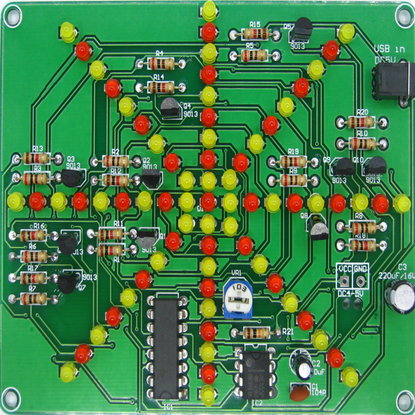
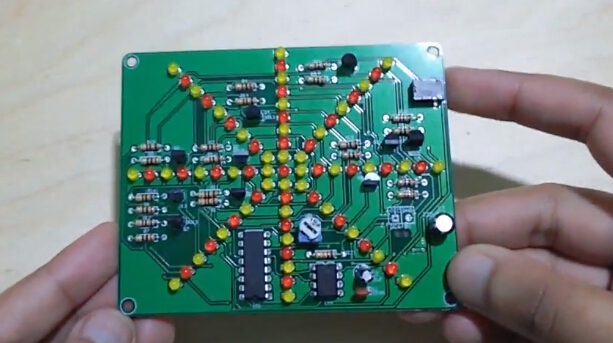
Finished Product Picture:
Tested by ICStation's Outstanding Partner The Unwanted Guy:
Learn More Details in the Video:


