
- prev
- next
74HC595 Static Drive 4 Segment Digital Display Module 0.5-inch 4 Digits Bright Red Display Board Module
$4.89$6.9930%
00d : 00h : 00m : 00s
Item ID: 8753
Product Details
Description:
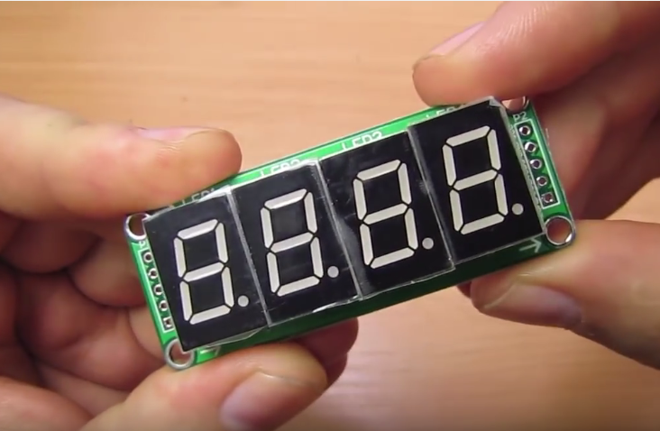
1>. 4-way bright red digital display module is easy to install with four screw holes.
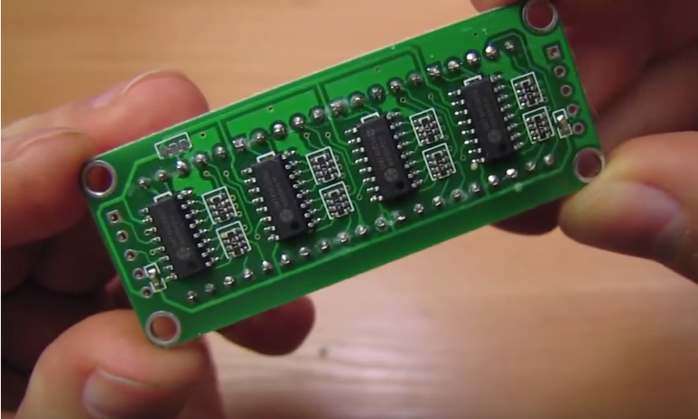
2>. Four 74HC595 SMD drives and digital tube were designed with each band limiting resistor, to ensure uniform brightness.
3>. Static drive in the digital is unchanged, and SCM has not been refreshed. Non-dynamic is scanned to save MCU system resources.
4>. Simple interface, VCC +, GND -, SDI data, Shift clock SCLK, latch LOAD, only three wire interface are connected with the microcontroller to save microcontroller IO.
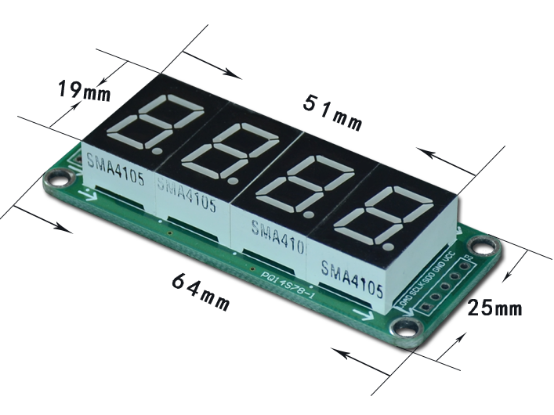
Product Size:
Tested by ICStation Outstanding Partner arduinoLab:
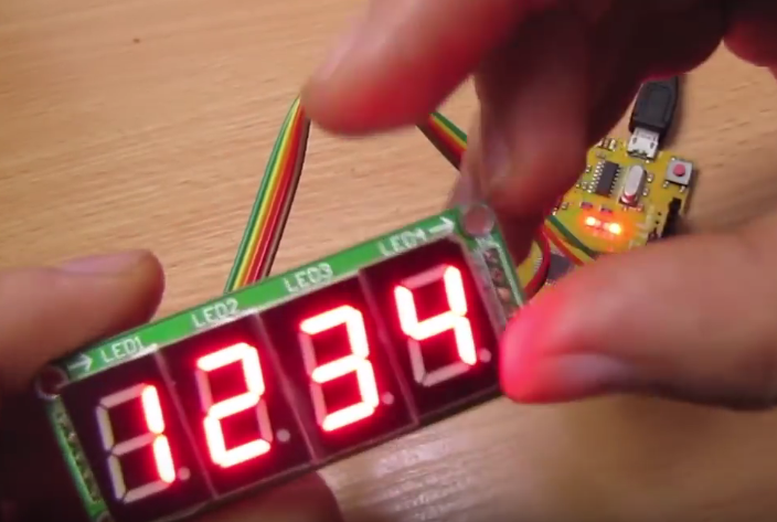
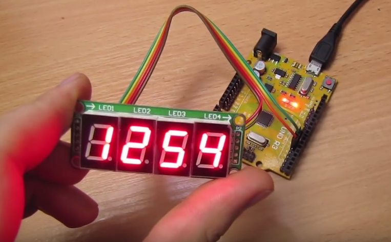
Learn More Details in the Video:
(The language in the video is Russian)
Customer Reviews (1)
-
By Russ Reiss2016-10-27 13:09:06
Really nice, easy to use product! With just five (5) pins to connect, two of which are +5v and GND, it's really easy to use. One input is SDAT, the other two are SCLK and LCLK. SCLK shifts the bit on SDAT into the left-most bit of the Shift Register, and shifts all the existing SR bits right one place. When you wish to update the output (display) you clock the LCLK pin and the current SR contents get loaded into the output/driver register for display. Each digit consists of seven (7) segments, plus there is a decimal point for each digit. This is eight (8) bits per digit... or 32 bits for the entire 4-digit display. It's simple to determine which bits control which segments (they're in a very conventional order). The MSB controls the decimal point. Keep in mind that a ZERO (0) turns a segment ON, while a ONE (1) turns it off. Your software can easily handle all that. When writing your control program, you must keep in mind that each of the last 32 bits you shifted in occupy some place in the SR. And when you pulse LCLK they will show up (at their current position) on the display. So you need to keep careful track of what you are shifting in and how much has been shifted. Shifting in 32 1's will clear all segments. The oldest data shifted in appears toward the right, while the newest enters from the left. You can daisy-chain multiple of these displays if desired. Using an Arduino UNO with no extra delays, I can load all 32 bits (segments) in under 500 usec. By pulsing the LCLK line just once after all 32 bits are shifted in, I get a really clean, crisp display with zero artifacts.


