- prev
- next
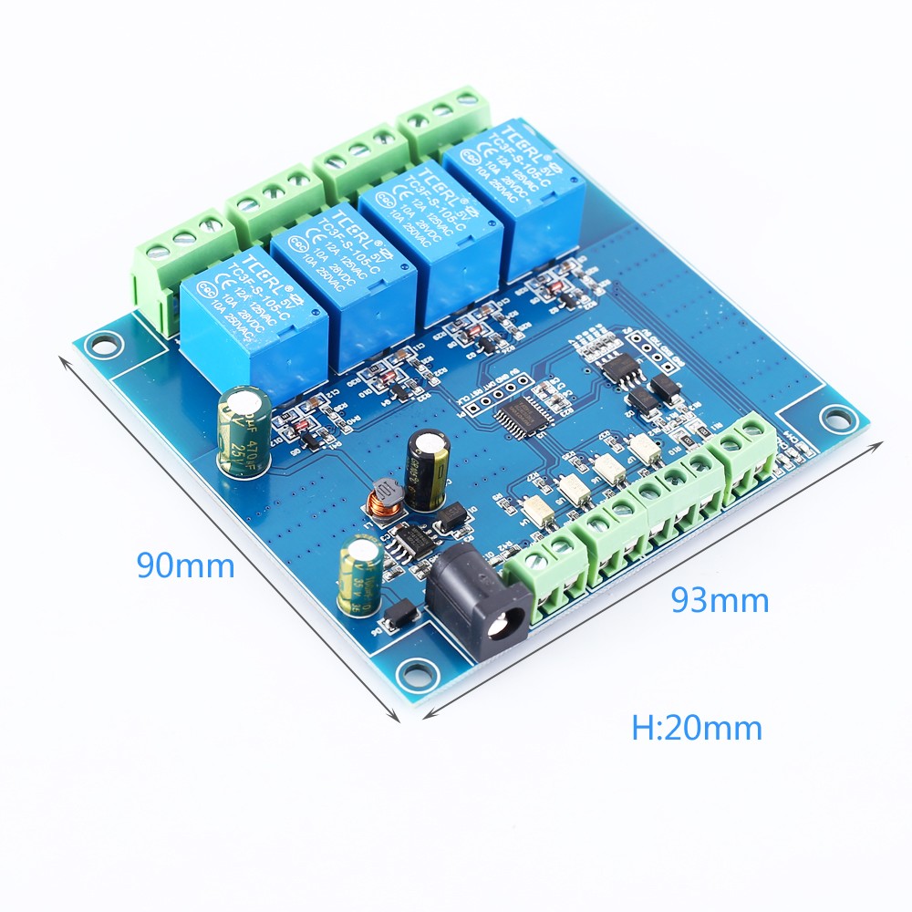
4 Channel Modbus Relay Module 4Bit Modbus-RTU Switch Signal Input Output RS485 TTL Controller
$11.99
Item ID: 15044
Product Details
1.Description:
LC 4 channel Modbus relay module equipped with mature and stable 8-bit MCU and RS485 level communication chip, adopt standard MODBUS RTU format RS485 communication protocol. It can realize 4bit input signal detection and 4bit relay output. It can be used for digital detection or power control occasions.
2.Features:
1>.Support Modbus RTU protocol
2>.Support RS485/TTL UART interface
3>.Output indicator in multi mode
4>.Address can be set
5>.Support input reverse connection protection
6>.Relay switch output
7>.Support parameter memory function
3.Parameters:
1>.Item name: 4-Channel Modbus Relay Module
2>.Work voltage:DC 7V~24V
3>.Baud rate:4800/9600/19600bps(default 9600bps)
4>.Optocoupler input signal:DC 3.3V~30V
5>.Set address:1~255
6>.Relay contorl mode: ON/OFF, Delay_ON, Delay_OFF mode
7>.Delay time: 0~6553.5s
8>.Load: AC 250V 10A or DC 28V 10A
9>.Protocol:Modbus RTU
10>.Interface:RS485/TTL UART
11>.Control channel: 4channel
12>.Operating Temperature:-20℃~85℃
13>.Operating Humidity:5%~95%RH
14>.Module Size:93*90*20mm
4.Modbus RTU Command:
1>.Suppose the device address is 0xFF so return 00 10 00 00 00 01 02 00 FF EB 80 and the 9th btye is device address.
2>.Turn ON CH_1 Relay(Normal Mode):
Send: FF 05 00 00 FF 00 99 E4
Return: FF 05 00 00 FF 00 99 E4
Note_1:The 3rd and 4th byte are relay addresses.So it can be 0x0000, 0x0001, 0x0002, 0x0003.
Note_2:The 5th and 6th byte are relay data. 0xFF00 means turn ON relay and 0x0000 means turn OFF relay.
3>.Turn OFF CH_1 Relay(Normal Mode):
Send: FF 05 00 00 00 00 D8 14
Return: FF 05 00 00 00 00 D8 14
4>.Turn ON CH_2 Relay(Normal Mode):
Send: FF 05 00 01 FF 00 C8 24
Return: FF 05 00 01 FF 00 C8 24
5>.Turn OFF CH_2 Relay(Normal Mode):
Send: FF 05 00 01 00 00 89 D4
Return: FF 05 00 01 00 00 89 D4
6>.Turn ON All relays:
Send: FF 0F 00 00 00 08 01 FF 30 1D
Return: FF 0F 00 00 00 08 41 D3
7>.Turn OFF All relays:
Send: FF 0F 00 00 00 08 01 00 70 5D
Return: FF 0F 00 00 00 08 41 D3
8>.Set device address to 0x01:
Send: 00 10 00 00 00 01 02 00 01 6A 00
Return: 00 10 00 00 00 01 02 00 01 6A 00
Note: The 9th btye is device address.
9>.Set device address to 0xFF:
Send: 00 10 00 00 00 01 02 00 FF EB 80
Return: 00 10 00 00 00 01 02 00 FF EB 80
10>.Read device address:
Send: 00 03 00 00 00 01 85 DB
Return: 00 03 02 00 FF C5 C4
Note: The 5th btye is device address.
11>.Read relay status:
Send: FF 01 00 00 00 08 28 12
Return: FF 01 01 01 A1 A0
Note:The 4th means which one relay. 0 means OFF and 1 means ON.
12>.Read optocoupler input staturs:
Send: FF 02 00 00 00 08 6C 12
Return: FF 02 01 01 51 A0
Note:The 4th means which one input. 0 means low level signal input and 1 means high level signal input.
13>.Set baud rate 4800bps:
Send: FF 10 03 E9 00 01 02 00 02 4A 0C
Return: FF 10 03 E9 00 01 C5 A7
Note:The 9th btye is baud rate value. 0x02 is 4800bps. 0x03 is 9600bps. 0x04 is 19200bps.
14>.Set baud rate 9600bps:
Send: FF 10 03 E9 00 01 02 00 03 8B CC
Return: FF 10 03 E9 00 01 C5 A7
15>.Set baud rate 19200bps:
Send: FF 10 03 E9 00 01 02 00 04 CA 0E
Return: FF 10 03 E9 00 01 C5 A7
16>.Turn ON CH_1 Relay(2S Flashing Mode):
Send: FF 10 00 03 00 02 04 00 04 00 14 C5 9F
Return: FF 10 00 03 00 02 A4 16
Note_1:The 3rd and 4th byte are relay addresses.So CH1~CH4 can be 0x0003,0x0008,0x000D,0x0012.
Note_2:The 10th and 11th byte are delay time in second.The minimum delay time is 0.1s. Relay will OFF after delay time.So the delay time in this command is : 0x0014*0.1=2S.
17>.Turn OFF CH_1 Relay(3S Flashing Mode):
Send: FF 10 00 03 00 02 04 00 02 00 1E A5 99
Return: FF 10 00 03 00 02 A4 16
Note:Relay will ON after delay time, so the delay time in this command is : 0x001E*0.1=3S.
5.Package:
1pcs 4CH Modbus Relay Module
.JPG)