- prev
- next
DIY Kit Electronic Dice Touch Control LED Lamp Circuit Experiment SMD Soldering Practice Kits
$4.99
| Quantity | 5+ | 10+ | 30+ |
| Price | $3.30 | $3.20 | $2.99 |
Item ID: GY17781
Product Details
1.Introduction:
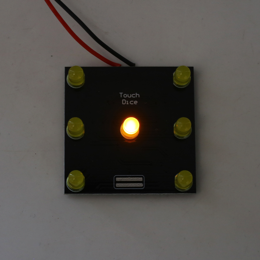
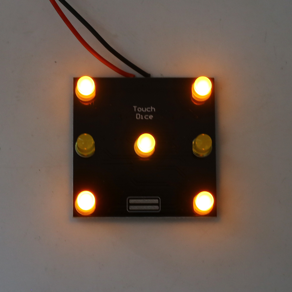
It is a touch-controlled electronic dice. The displayed numbers are randomly displayed after each press of the touch button.
2.Feature:
1>.Touch button control
2>.Electronic simulation dice
3>.SMD soldering practice
3.Parameter:
1>.Work Voltage:DC 9V
2>.Work Current:50mA
3>.Work Module:Touch Button Control
4>.Work Temperature:-40℃~85℃
5>.Work Humidity:0%~95%RH
6>.Size(Installed):40*40*11mm
4.Installation Tips:
1>.User needs to prepare the soldering tool at first.
2>.Please be patient until the installation is complete.
3>.The soldering iron can't touch the components for a long time(1.0 second), otherwise it will damage the components.
4>.Pay attention to the positive and negative of the components.
5>.Strictly prohibit short circuit.
6>.User must install the LED according to the specified rules.Otherwise some LED will not light.
7>.Install complex components preferentially.
8>.Make sure all components are in right direction and right place.
9>.Check that all of the LED can be illuminated.
5.Installation Steps(Please be patient):
.png)
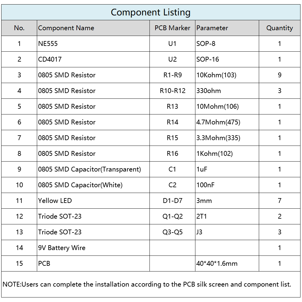
Step 1: Install 1pcs CD4017 SOP-16 at U2.There is a dot on one corner of the IC and there is a white dot on PCB where the IC can place on.These two marks are corresponding to each other and are used to specify the installation direction of the IC.
Step 2: Install 1pcs NE555 SOP-8 at U1 as the same method.
Step 3: Install 3pcs J3 Triode SOT-23 at Q3-Q5.
Step 4: Install 2pcs 2T1 Triode SOT-23 at Q1-Q2.
Step 5: Install 9pcs 10Kohm(103) 0805 SMD Resistor at R1-R9.
Step 6: Install 3pcs 330ohm 0805 SMD Resistor at R10-R12.
Step 7: Install 1pcs 10Mohm(106) 0805 SMD Resistor at R13.
Step 8: Install 1pcs 4.7Mohm(475) 0805 SMD Resistor at R14.
Step 9: Install 1pcs 3.3Mohm(335) 0805 SMD Resistor at R15.
Step 10: Install 1pcs 1Kohm(102) 0805 SMD Resistor at R16.
Step 11: Install 1pcs 1uF 0805 SMD Capacitor which in the transparent shell at C1.
Step 12: Install 1pcs 100nF 0805 SMD Capacitor which in the white shell at C2.
Step 13: Install 7pcs 3mm Yellow LED at D1-D7.
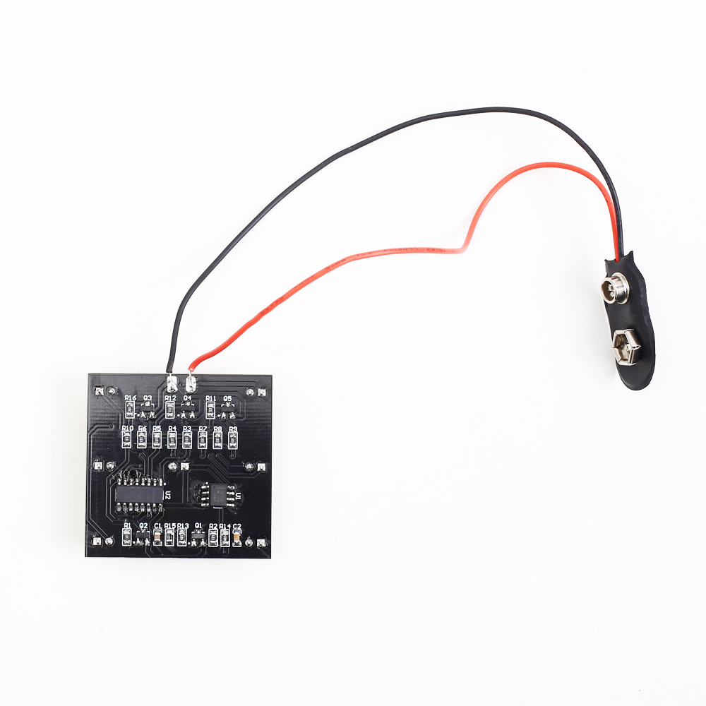
Step 14: Install 9V battery socket.
Step 15: Connect to power supply and enjoy the LED flashing effect. Press touch button to change display effect.
.jpg)