
- prev
- next
Infrared Reversing Indicator DIY Kit Adjustable Infrared Sensor Distance Measuring Module
Product Details
Description:
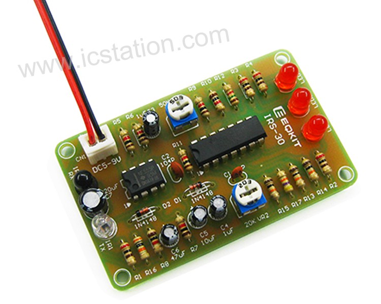
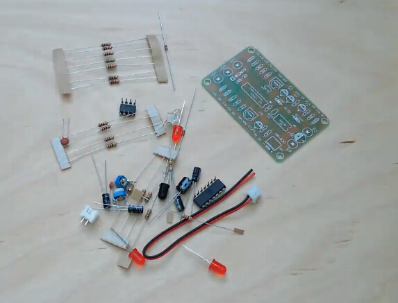
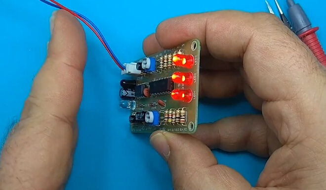
This is a DIY Infrared Reversing Indicator kit parts. You should solder it by yourself. According to the infrared reaction, measure the distance and change the output transition.It can be applied to intelligent robots, smart homes, industrial controls and so on.
Features:
1>. High sensitivity;
2>. Short sensing distance;
3>. Low power consumption;
4>. Inductive distance adjustable;
5>. Working status indicator;
6>. Wide operating voltage range;
7>. Low power consumption;
8>. DIY design.
Parameters:
| No. | Parameter | Value |
| 1 | Model | IRS-30 |
| 2 | Standby current | Less than 15mA |
| 3 | Soldering difficulty Level | Easy |
| 4 | Working voltage | DC 5V-9V(Recommend 5V) |
| 5 | Working current | Less than 90mA |
| 6 | PCB Size | 67*41mm |
Working principle:
1>.When light hits the surface of the object, it radiates and emits part of the light. Through this principle, the receiver is used to receive this portion of the light to output a signal. According to a series of circuits, the distance range is indicated by an indicator.
2>.This circuit uses the modulated invisible infrared to detect the distance and has the advantage of anti-interference!
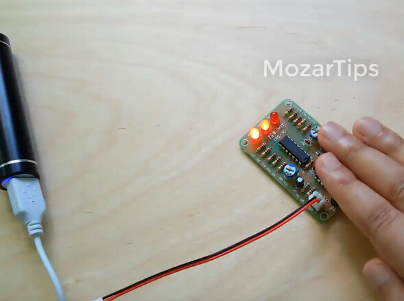
3>.When the object is in front of the light source about 30cm,LED3 will ON;When the object is in front of the light source about 20cm,LED2 will ON;When the object is in front of the light source about 10cm,LED1 will ON;
4>.The working voltage of this kit is DC5-9V, the recommended voltage is 5V.
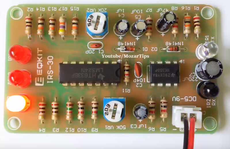
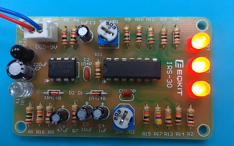
Potentiometer Description:
There are two potentiometer on PCB. They have different function as shown:
VR1 : It is used to adjust distance.
VR2 : It is used to adjust sensitivity regulation.
Instructions:
Step 1: Complete the installation in the normal way following installation manual and schematic.(Please request separately).
Step 2:Connect DC 5-9V voltage;
Step 3:Adjust two potentiometers for test distance and sensitivity regulation.
Step 4:Test and use.
Using Attention:
1>.It cannot be used directly under the sun because it uses infrared testing.
2>.It cannot be used in high temperature environments and can be disturbed.
3>.Please make sure all components in right direction and right place.
4>.Please check whether pseudo/float welding.This is very important .
5>.The soldering iron can't touch the components for a long time, otherwise the components will be damaged because of the high temperature.
Component List:
| NO. | Component Name | PCB Marker | Parameter | Quantity |
| 1 | Metal Film Resistor | R1-R4 | 200ohm | 4 |
| 2 | Metal Film Resistor | R5-R11 | 1K | 7 |
| 3 | Metal Film Resistor | R12 | 1.5K | 1 |
| 4 | Metal Film Resistor | R13-R15 | 10K | 3 |
| 5 | Metal Film Resistor | R16 | 30K | 1 |
| 6 | Metal Film Resistor | R17 | 47K | 1 |
| 7 | Ceramic Capacitor | C1 | 20P | 1 |
| 8 | Ceramic Capacitor | C2 | 104P | 1 |
| 9 | Electrolytic Capacitor | C3-C4 | 1uF | 1 |
| 10 | Electrolytic Capacitor | C5 | 10uF | 1 |
| 11 | Electrolytic Capacitor | C6 | 47uF | 1 |
| 12 | Electrolytic Capacitor | C7 | 220uF | 1 |
| 13 | Diode | D1-D2 | 1N4148 | 2 |
| 14 | 5mm LED | LED1-LED3 | Red | 3 |
| 15 | Infrared Emitter | IR1 | 5mm White | 1 |
| 16 | Infrared Receiver | IR2 | 5mm Black | 1 |
| 17 | Potentiometer | VR2 | 20K | 1 |
| 18 | Potentiometer | VR1 | 50K | 1 |
| 19 | NE555 | U1 | DIP-8 | 1 |
| 20 | LM324 | U2 | DIP-14 | 1 |
| 21 | 2P Socket | CN1 | 2.54mm | 1 |
| 22 | Cable | CN1 | 2P 15cm | 1 |
| 23 | PCB | IRS-30 | 64*41mm | 1 |
Note: You can finish installation by PCB silk screen and component listing.
Application:
1>.Smart home
2>.Smart robot
3>.Distance alarm
Example:
It can be used in Robot Competition.The robot advances in the maze and changes direction according to obstacles ahead to avoid collision obstacles.
Frequency asked questions:
1>. Why can't work?
Q :Please make sure all components in right direction and right place and check whether pseudo/float welding.This is very important.
2>. Can I measure distances over 30cm??
Q :Sorry,it can not.
Install tools you need preliminary preparation by yourself:
1>. Soldering iron;
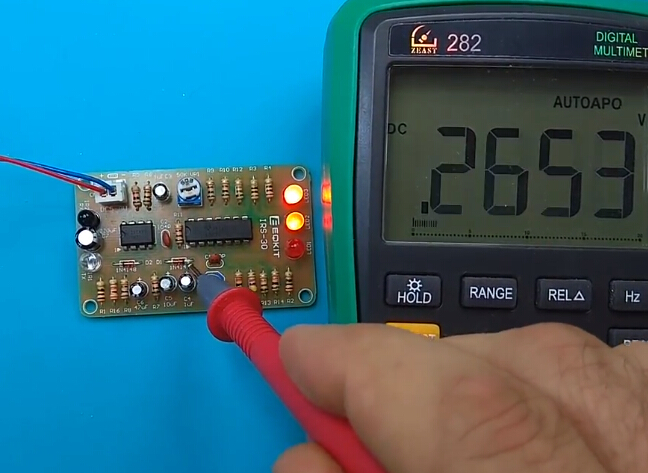
2>. Multimeter;
3>. Solder wire;
4>. Iron stand;
5>. Diagonal cutting pliers;
6>. The screwdriver;
7>. Tweezers;
8>. Long nose pliers;
9>. Suction tin;
10>. Cleaning sponge;
11>. Screwdriver set.
Download installation manual and schematic:
.png)
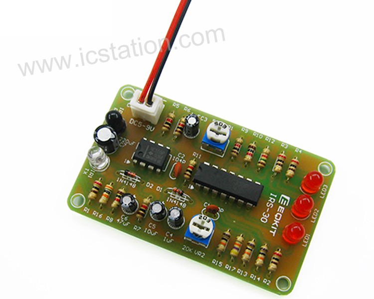
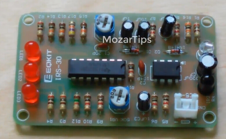
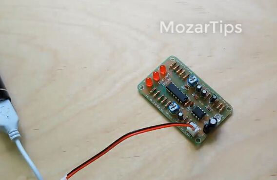
Finished Product Picture:
I. Tested by ICStation's Outstanding Partner The Unwanted Guy:
Learn More Details in the Video:
(The language in the video is English)
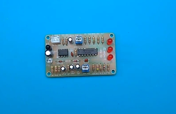
II. Tested by ICStation's Outstanding Partner bzoli5706:
.jpg)
.jpg)
Learn More Details in the Video:
(The language in the video is English)


