- prev
- next
DIY Kit RGB LED Flashing Controller SMD Component Welding Practice Electronic Suite
$3.75
| Quantity | 50+ |
| Price | $1.95 |
Item ID: 13606
Product Details
Description:
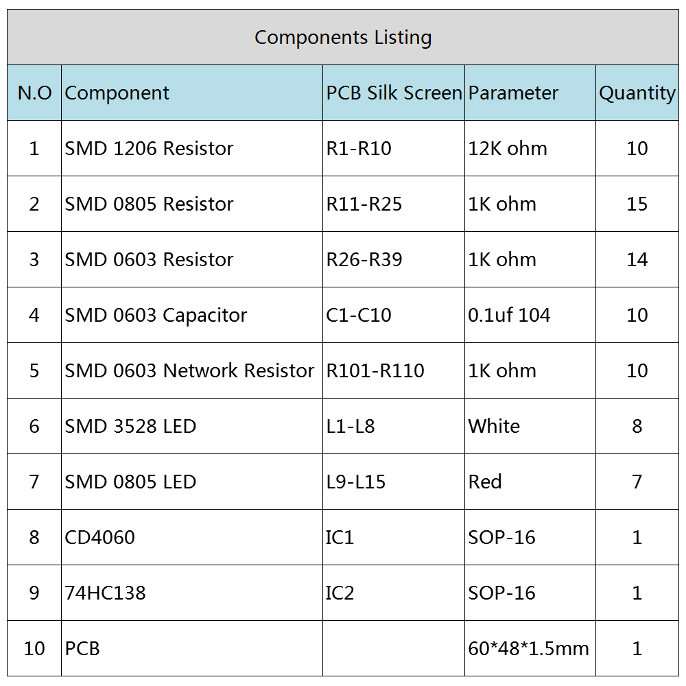
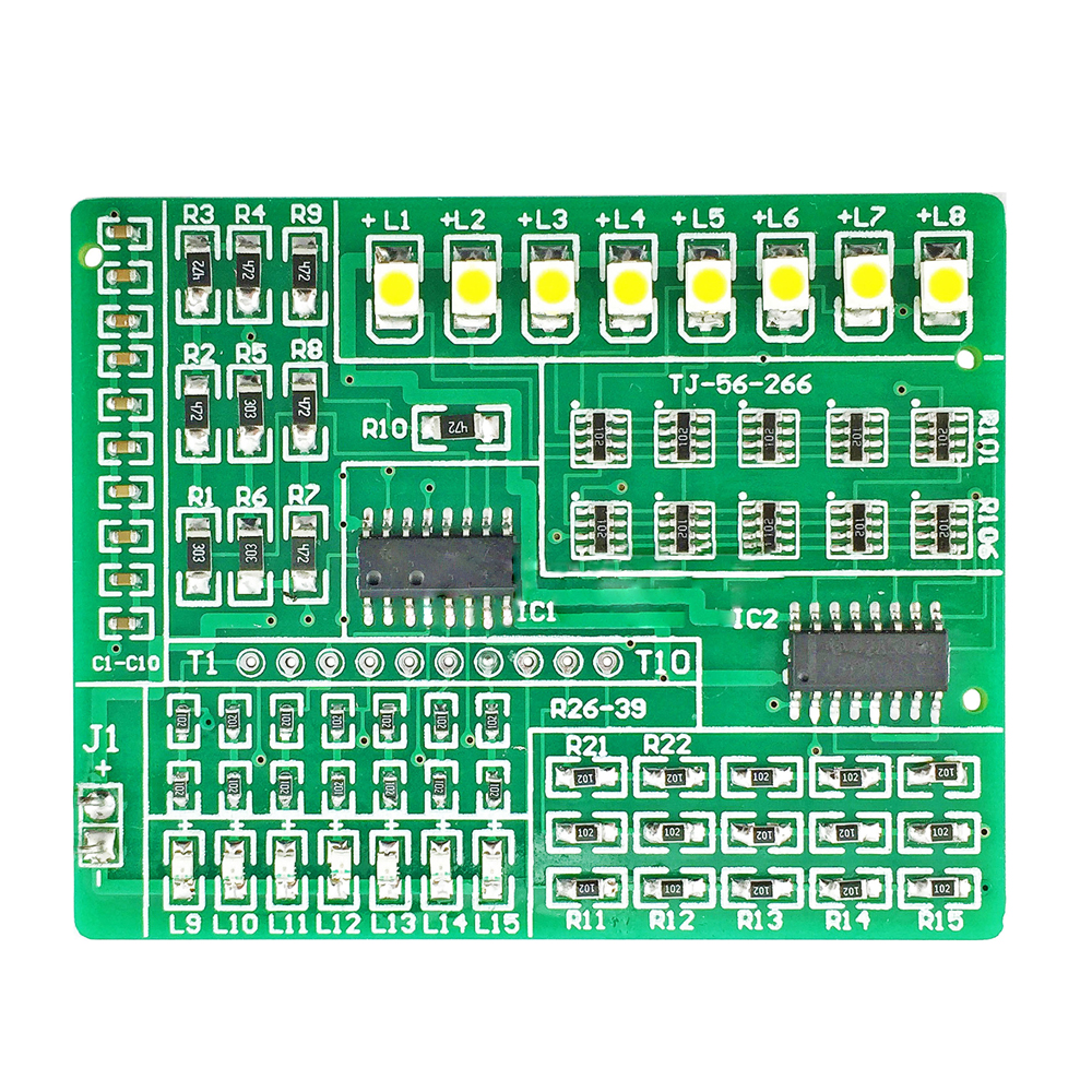
In order to improve the welding skill level of electronic professional students and electronic enthusiasts, the full patch design, welding quality can be visually displayed through the lighting of 15 LEDs.
The circuit is novel, interesting, and complete in components. It adopts double-sided glass fiber tin plate, which is intended to improve the welding level and speed.
Circuit Introduction:
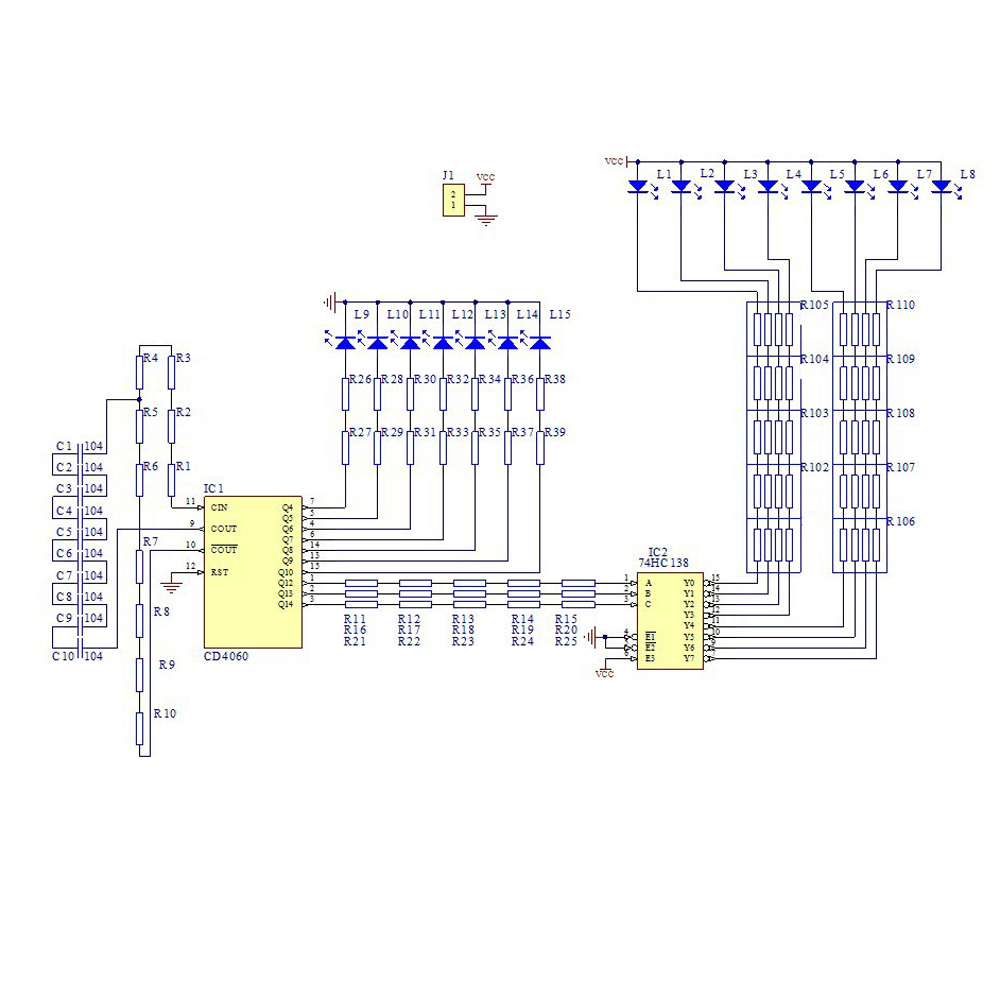
This circuit is an LED automatic control circuit composed of digital integrated circuits CD4060 and 74HC138. The CD4060 is internally composed of an oscillator and a binary counter with 10 outputs. The external oscillator can be connected to a crystal oscillator or RC.
The control circuit is connected as RC. Oscillation mode, R1-R10 series and C1-C10 are connected in series. The resistance of the series resistor is the sum of the resistance values of the resistors. The series capacitance of the same capacitor is equal to the capacity of a single capacitor/capacitor, 104/10.
After the CD4060 oscillator circuit starts to oscillate, the counter counts the oscillating signal, and each bit of the counter continuously flips with the count, thereby outputting a square wave signal with a frequency from high to low on the pins Q4-Q14, where Q4-Q10 Each of the light-emitting diodes L9-L15 is driven such that the seven light-emitting diodes produce flicker of different frequencies.
Q12-Q14 is connected to the input terminal of integrated circuit 74HC138, 74HC138 is 3-8 line decoding circuit, only one bit is low level at the output end. As the data at the input changes, Y0-Y7 sequentially becomes a low level, thereby forming a water-light effect on L1-L8. When the CD4060 overflows, it will become 0 again. Thereby achieving automatic control of 15 LEDs.