- prev
- next
DIY Kit Infrared Sensor Alarm Electronic Circuit Learning Soldering Practice Kit
$3.35
Item ID: 13808
Product Details
Descrption:
This circuit design can realize the buzzer sounds when the hand is close to the infrared emission tube and the infrared receiving tube, the LED light is on, the sound is stopped immediately after the hand is removed, the LED light is extinguished, and the sensitivity is very high.
The circuit design idea comes from the life scene where the bank automatically opens and closes the door. When people enter the bank, the door automatically opens and the door closes automatically. Or the faucet from a high-end restaurant such as KFC, when the hand is placed under the faucet, the water automatically flows out, and the water automatically closes after leaving.
There are many life scenarios in this circuit application, which is a circuit that circuit designers must master. The infrared sensing circuit is mainly used to learn the working principle and usage method of the infrared transmitting tube and the infrared receiving tube, and at the same time grasp the practical application of the general-purpose operational amplifier LM358 as an arithmetic comparator.
After the circuit is successfully manufactured, it must be debugged to achieve the corresponding effect. Only after understanding the working principle of the infrared sensing circuit can the relevant parameters be debugged.
Parameter:
Work voltage:DC 5V
Characteristics:
It is processed by 1.5mm high-quality electric wood board, the pad is enlarged, the wire is thicker, and the component layout is beautiful. It is specially designed for the training, and it is easy to withstand repeated and repeated desoldering, which can improve the use efficiency and high cost performance.
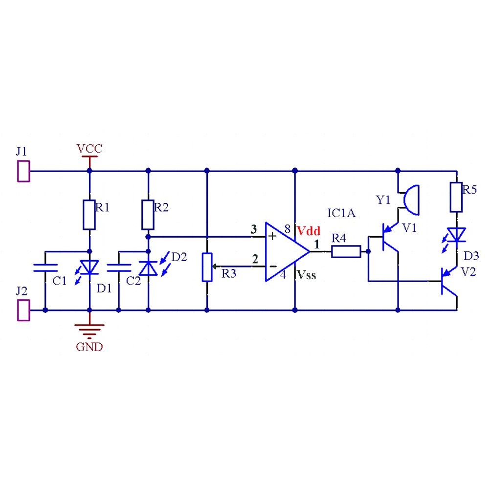
Principle:
The 5V power supply is connected, the infrared emission tube D1 is turned on, and the infrared light is emitted (the eyes are invisible). If the light is not blocked by the hand at this time, the infrared receiving tube D2 does not receive the infrared light, and the infrared receiving tube D2 Still in the reverse cutoff state. The voltage at the negative terminal of the infrared receiving tube D2 is still high and sent to the 3 pin of the LM358.
The voltage of pin 2 of LM358 depends on adjustable resistor R3. As long as the adjustable resistor R3 is adjusted to the appropriate time (measuring the voltage of pin 2 of LM358 with a multimeter is about 2.5V), the voltage of pin 3 of LM358 can be guaranteed to be greater than The voltage of pin 2 of LM358, according to the working principle of the comparator, when V+ > V-, the 1 pin of LM358 will output a high level, and will be sent to the base of PNP type transistors V1 and V2 through current limiting resistor R4. , causing the transistors V1, V2 to be turned off, the buzzer Y1 does not sound, and the light-emitting diode D3 is extinguished.
When the hand is close to the infrared emission tube D1, the infrared light is blocked and reflected to the infrared receiving tube D2, and the infrared receiving tube D2 receives the infrared light and is turned on immediately, so that the voltage of the negative electrode of the infrared receiving tube D2 drops rapidly. Send it to the 3 feet of the LM358.
The voltage of pin 3 of LM358 drops to less than the voltage of pin 2. According to the working principle of the comparator, when V+ < V-, pin 1 of LM358 will output low level and send it to PNP type transistor through current limiting resistor R4. The bases of V1 and V2 cause the transistors V1 and V2 to turn on the buzzer Y1 and the LED D3 to illuminate.
Through the above debugging, when the hand moves to the upper side of the infrared transmitting tube D1 and the infrared receiving tube D2, the buzzer sounds and the light emitting diode lights up. When the hand leaves the infrared transmitting tube D1 and the infrared receiving tube D2, the buzzer stops sounding, and the light emitting diode is extinguished, which produces an effect of sensing the hand.