- prev
- next
DIY Kit SMD Infrared Distance Sensor Indicator Soldering Practice Kits
$2.79$3.9930%
| Quantity | 10+ | 30+ | 50+ |
| Price | $2.79 | $2.70 | $2.50 |
00d : 00h : 00m : 00s
Item ID: 13612
Product Details
Description:
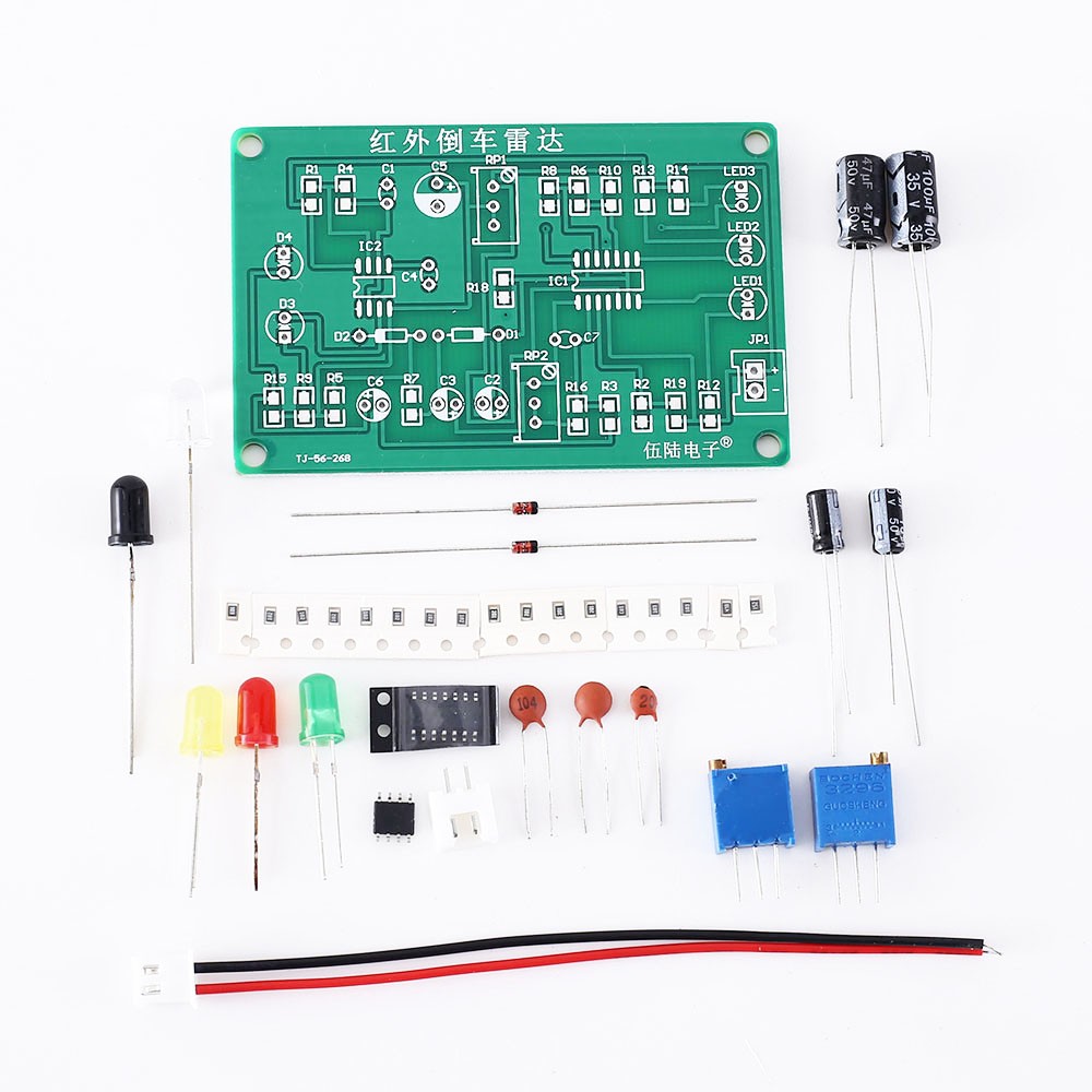
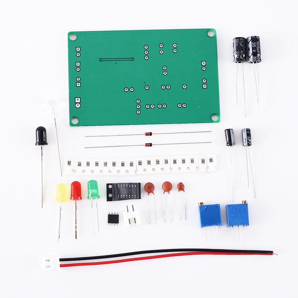
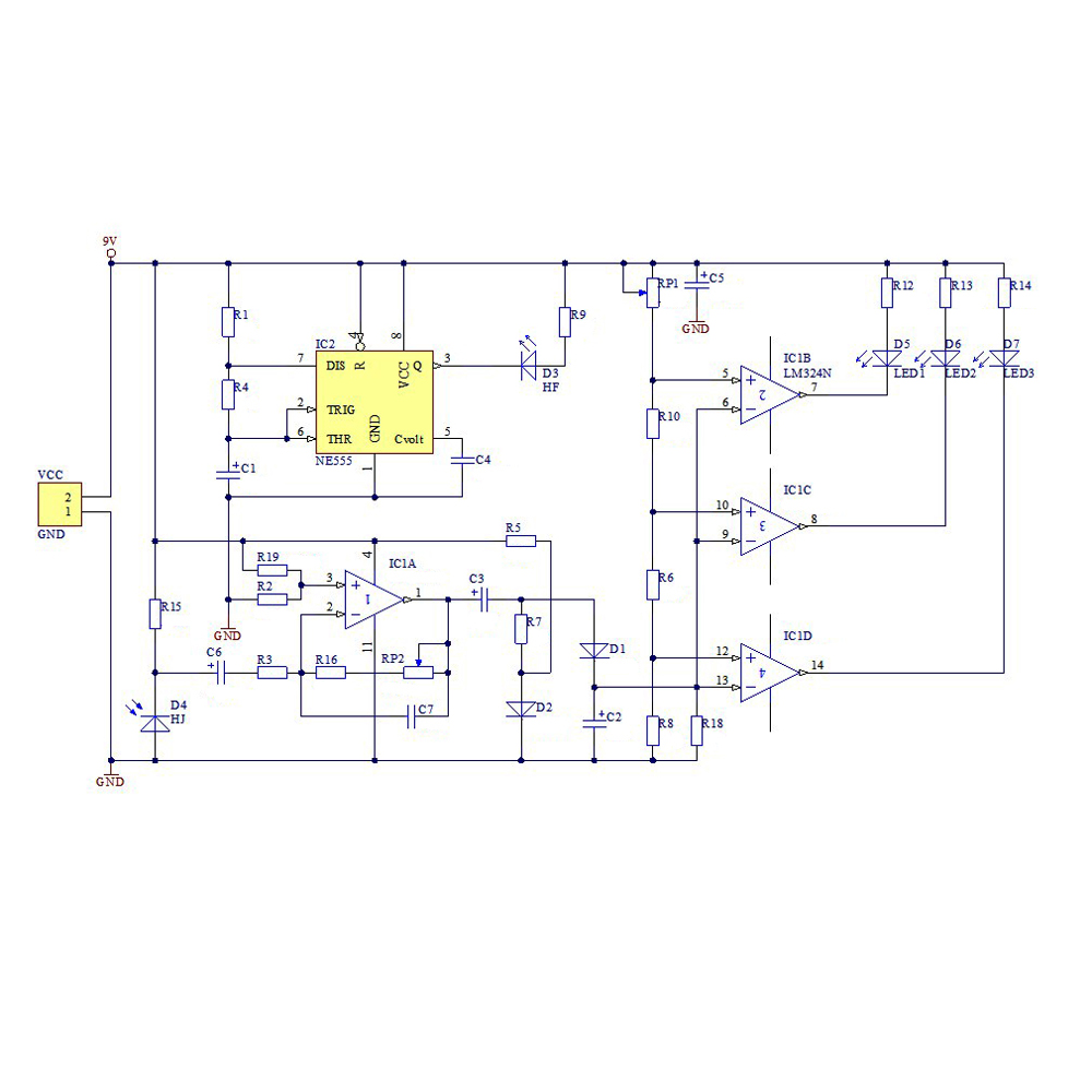
The infrared reversing radar is composed of a multi-resonant circuit, an infrared signal transmitting and receiving circuit, an infrared signal amplifying and a voltage comparison circuit.
It has the characteristics of simple circuit, low cost and stable circuit operation which is widely used in various ranging occasions.
Parameter:
Working voltage: DC9V
Principle description
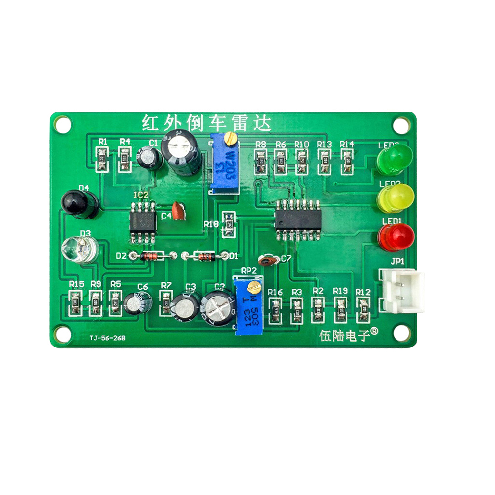
1.The infrared transmitting tube HF and the infrared receiving tube HJ have polarity (long legs are positive), please do not install the wrong ones, the mounting direction can be upwards or sideways.
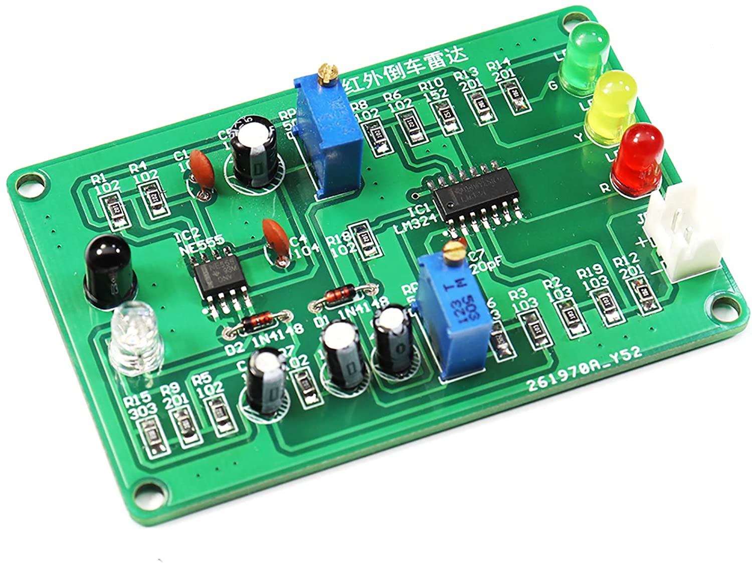
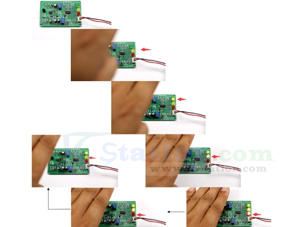
RP1 adjusts the reflection distance, RP2 adjusts the sensitivity, LED3 can be bright when the distance is 30cm, LED2 and LED3 are bright when the distance is 20cm, and fully bright when the distance is 10cm. It is better to use a white paper to block the reflection above the infrared sensor.
2.The time base circuit NE555 and surrounding components form a multivibrator to generate an infrared wave signal, which is output through the third pin of IC2 and drives the infrared transmitting tube HF to emit an infrared signal.
Installation Notes:
1.The infrared emission tube (HFS) and the infrared receiving tube (HS) have polarity, and the polarity direction is determined before installation.The mounting direction can be either upward or sideways.
2.The light-emitting diode and diode 1N4148 have polarity, and the polarity direction is determined before installation.
3.The integrated block is soldered to the base first, and the polarity direction is paid attention to when installing the chip.
4.The circuit has no power polarity protection. Before the power is turned on, the positive and negative poles are determined.
5.Rp1 adjusts the reflection distance, Rp2 adjusts the sensitivity, you can try 30cm one light, 20cm two lights, 10cm three lights. The top of the sensor is covered with white paper, which has the best reflection on infrared waves.