
- prev
- next
DIY Kit Photoelectric Multi-function Light Control Automatic Switch
| Quantity | 10+ | 30+ | 50+ |
| Price | $1.50 | $1.30 | $1.15 |
Product Details
Function:
The circuit can automatically open and close related appliances according to the brightness of light. Its output is controlled by the relay, which can directly replace the original manual switch. (If you replace the photosensitive resistance of this circuit with other sensitive resistors, you can make other automatic switches, such as temperature control switches, etc.).
Working Voltage:
5-12V is available. The coil voltage of the relay is 5V by default and the measured working voltage is 4-12V. If you work long hours in high voltage conditions, recommend replacing the relay with 9-12V.
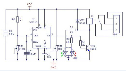
Circuit Principle:
It is the Schmitt trigger of the circuit with the circuit U1 at the base of NE555.The photosensitive resistor is the input signal of the RP1 series.Adjusting RP1 can change the light intensity control point.C1 is the interference signal absorption capacitance.
When the light is very bright in the daytime, the RG resistance is small, the input voltage is higher than the reference voltage voltage (5 feet pin), the output low level 3 feet pin, VT1 cut-off, relay doesn't work, losing electricity output switch (1, 2 feet of JP1), with electric does not work. When the light dimmed, RG resistance increasing, the input voltage is falling, when the voltage is less than half of the reference voltage, the trigger flip, 3 feet, output level VT1 conduction, relay electric off, with electric start work.
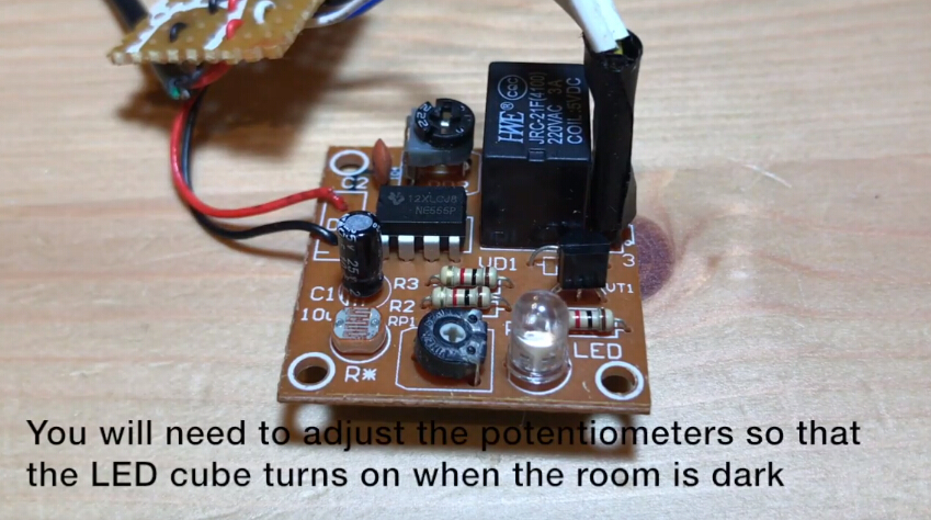
When the input voltage is between the reference voltage and the reference voltage of 1/2, the circuit maintains its original state.This is conducive to the stability of the circuit. Adjusting RP2 can change the reference voltage, thus changing the control brightness range and the starting point.The RP2 and RP1 need to be adjusted repeatedly to achieve the required degree.
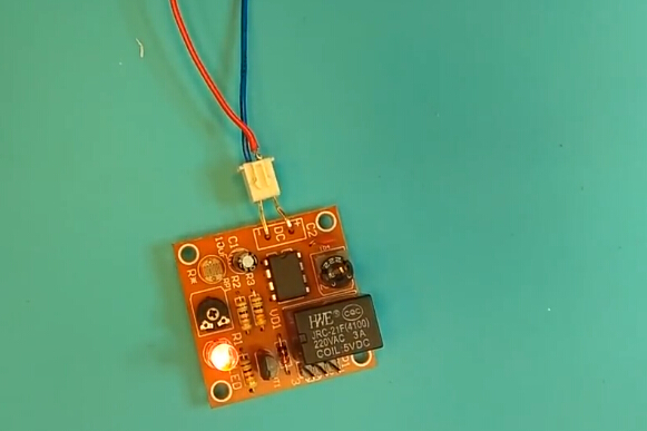
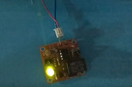
Switch signal output from JP1, its often opened on the choice of normally closed contact according to the need to be sure, can be directly driven 220 V/prefix = st1 ns = "urn: schemas - Microsoft - com: office: smarttags" any electrical appliances within 3A, to achieve automatic switch (such as street lamps, etc.). The LED is a dual-color, and the relay fails to absorb the red light and is used as a power indicator. After the relay is closed, the red light is out and the light is green.
Circuit Diagram:
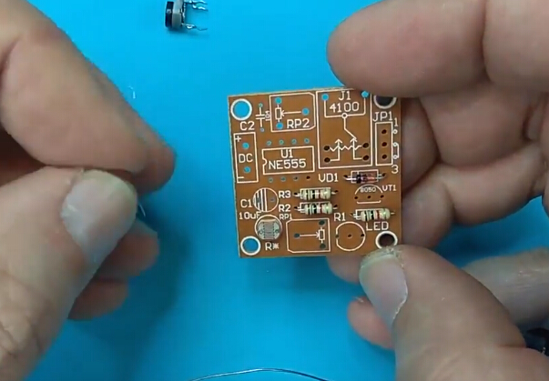
Component Listing:
| NO. | Component Name | PCB Marker | Parameter | QTY |
| 1 | Metal Film Resistor | R1-R3 | 1K | 3 |
| 2 | Ceramic Capacitor | C2 | 0.1uf | 1 |
| 3 | 1N4148 | VD1 | 1 | |
| 4 | Electrolytic Capacitor | C1 | 10uf | 1 |
| 5 | S8050 | VT1 | TO-92 | 1 |
| 6 | Photoresistance | RG | 1 | |
| 7 | Potentiometer | RP1 | 135K | 1 |
| 8 | Potentiometer | RP2 | 2.2K | 1 |
| 9 | LED | LED | 5mm | 1 |
| 10 | NE555 | U1 | DIP-8 | 1 |
| 11 | Relay | J1 | 1 | |
| 12 | Male Pin | JP1 | 3P | 1 |
| 13 | PCB | 34*35mm | 1 |
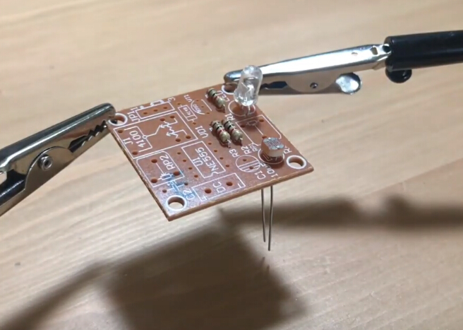
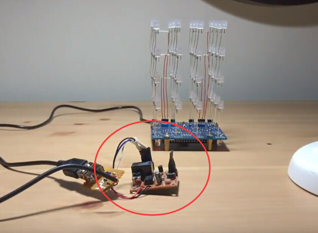
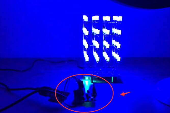
I. Tested by ICStation's Outstanding Partner bzoli5706:
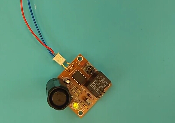
Learn More Details in the Video:
(The language in the video is English)
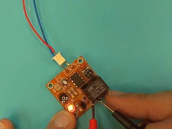
II. Tested by ICStation's Outstanding Partner Lukas Ekers:
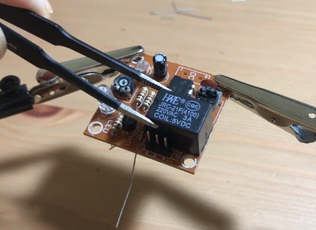
Learn More Details in the Video:
(The language in the video is Music)


