
- prev
- next
DIY Kit Infrared Remote Control Lamp DC 5V-6V LED Light Soldering Practice Kit
$7.35$10.5030%
00d : 00h : 00m : 00s
Item ID: GY20030
Product Details
RNT-8 Infrared Remote Control Lamp DIY Kit
Reviewed by ICStation Outstanding Partner:
1.Introduction:
RNT-8 is a DC 5V-6V Infrared Remote Control Lamp DIY Kit. User can use any infrared remote controller to control the lamp on or off with 8pcs white LED.
2.Parameter:
- Product Name:RNT-8 Infrared Remote Control Lamp DIY Kit
- Product Number:RNT-8
- Work Voltage:DC 5V-6V
- Power Type:USB or Battery(Not Included!)
- Work Mode:Switch or Infrared Remote Control
- Color:White LED
- Work Temperature:-25℃~85℃
- Work Humidity:5%~95%RH
- Size(Installed):74.2*74.2*54mm
3.Function:
- Black button on PCB is used to turn ON or OFF lamp.
- Any infrared remote controller to control the lamp on or off.
- Note:The batteries must be removed when using USB power supply.
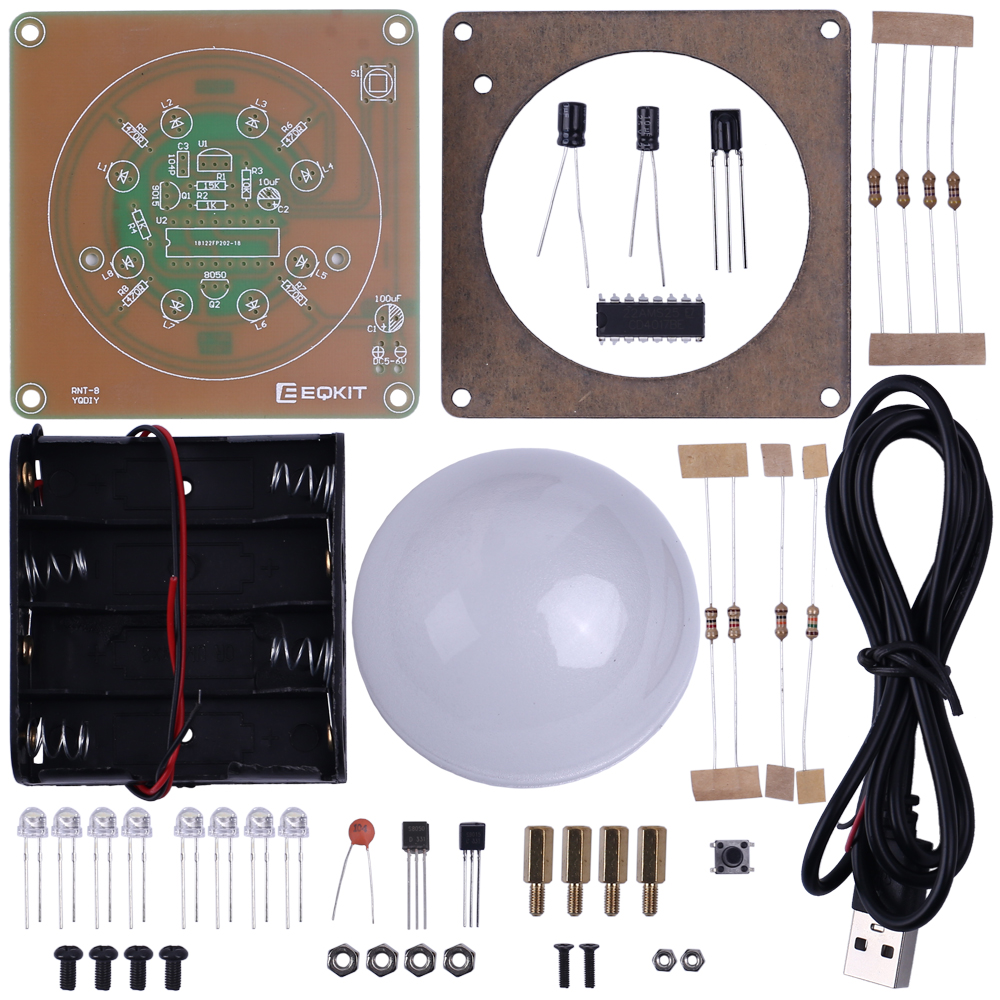
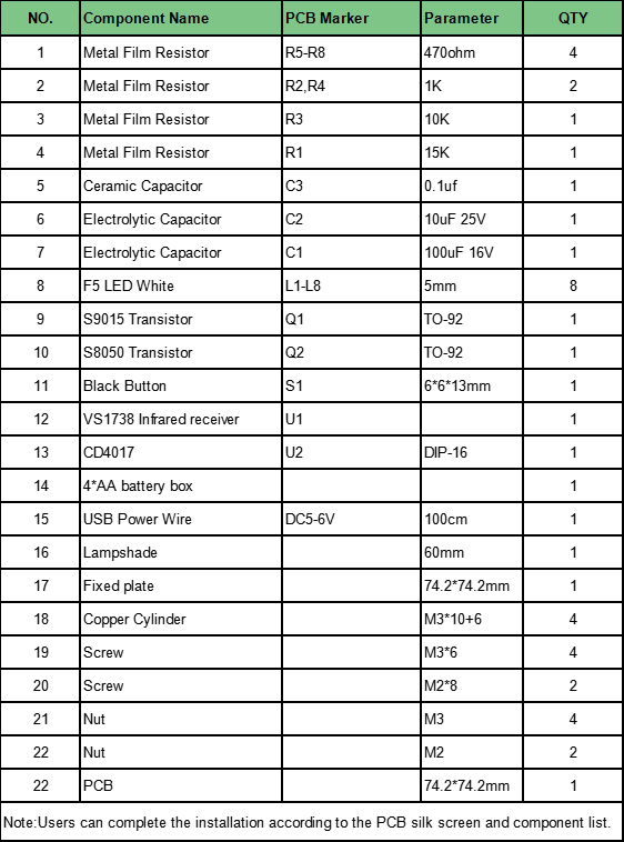
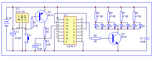
4.Component List and Circuit:
5.Installation Tips:
1.User need to prepare the welding tool at first.
2.Please be patient until the installation is complete.
3.The soldering iron can't touch the components for a long time(1.0 second), otherwise it will damage the components.
4.Pay attention to the positive and negative of the components.
5.Strictly prohibit short circuit.
6.User must install the LED according to the specified rules. Otherwise some LED will not light.
7.Install complex components preferentially.
8.Make sure all components are in right direction and right place.
9.Check that all of the LED can be illuminated.
10.Please wear anti-static gloves or anti-static wristbands when installing electronic components.
6. Installation Steps:
Step 1: Install 4pcs 470ohm Metal Film Resistor at R5-R8.
Step 2: Install 2pcs 1Kohm Metal Film Resistor at R2,R4.
Step 3: Install 1pcs 10Kohm Metal Film Resistor at R3.
Step 4: Install 1pcs 15Kohm Metal Film Resistor at R1.
Step 5: Install 8pcs 5mm F5 White LED at L1-L8.The longer pin is inserted into the inner ring pad(positive pole). The shorter pins are inserted into the outside ring pads.
Step 6: Install 1pcs DIP-16 CD4017 IC at U6.There is a mark on one end of the IC and there is a mark on PCB where the IC can place on.
These two marks are corresponding to each other and are used to specify the installation direction of the IC.
Step 7: Install 1pcs 0.1uF 104 Ceramic Capacitor at C3.
Step 8: Install 1pcs TO-92 S9015 Transistor at Q1.
Step 9: Install 1pcs TO-92 S8050 Transistor at Q2.
Step 10: Install 1pcs VS1738 Infrared receiver at U2. Pay attention to the installation direction.
Step 11: Install 1pcs 10uF 25V Electrolytic Capacitor at C2. Pay attention to distinguish between positive and negative. The Longer pin is positive pole.
Step 12: Install 1pcs 100uF 16V Electrolytic Capacitor at C1.
Step 13: Install 1pcs 6*6*13mm Black Button at S1.
Step 14: Install 1pcs 4*AA battery box or USB Power Wire at DC5-6V. Red wire connect to ‘+’ and black wire connect to ‘-’.
Note: It is recommended to connect to only one of the power supply methods.
Step 15: Fix battery box by 2pcs M2*8 Screw and 2pcs M2 Nut if installed battery box.
Step 16: Install 4pcs M3*10+6 Copper Cylinder and 4pcs M3 Nut on PCB. May need to adjust the nut position.
Step 17: Tear off the protective film on the black acrylic surface.
Step 18: Install Lampshade and fixed by Fixed plate and M3*6 Screw.
Step 19: Install 4pcs 1.5V AA battery(not included) or connect USB power and then press button to switch lamp.
Please download the installation manual with more details here:
.png)


