
- prev
- next
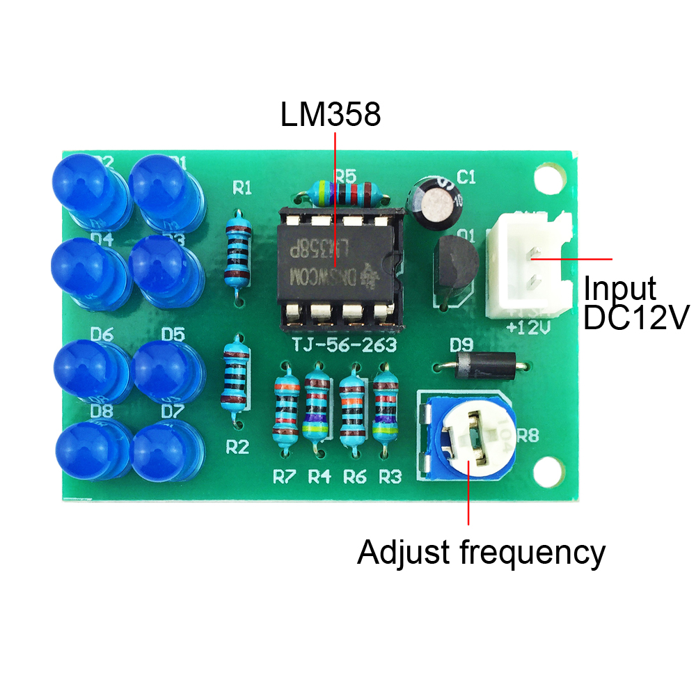
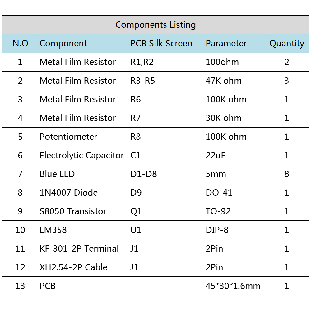
DIY Kit LM358 Breathing Light Adjustable DC 12V Electronic Components Soldering Practice Kits
$1.99
| Quantity | 5+ | 10+ |
| Price | $1.25 | $1.19 |
Item ID: 13611
Product Details
Description:
The light changes from bright to dark, and then gradually changes from dark to bright, feeling like a person is breathing. Widely used in digital products, computers, audio, automotive and other fields, has played a very good visual decorative effect.
Parameter:
Power supply voltage: DC12V
Main control chip: LM358
Luminous color: bright blue light
Number of LEDs: 8pcs
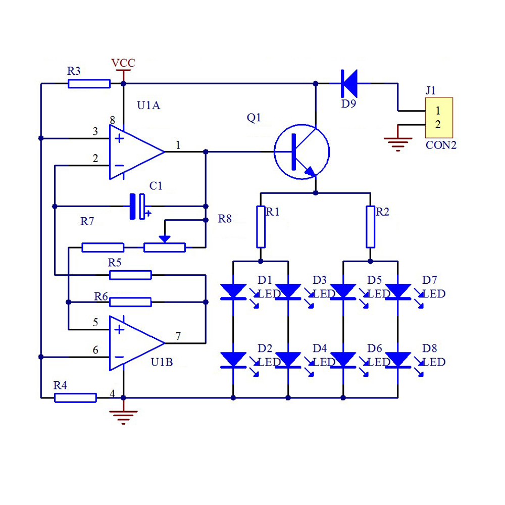
Working principle analysis:
Step 1: At this time, C1 is equivalent to a short circuit, and the output of U1A is equal to the voltage of the third pin of U1A;
Step 2: This voltage is sent to U1B below. The following positive feedback circuit causes the following U1B output to be high; the high level voltage is +VCC.
Step 3: When the U1B output is VCC voltage, the voltage difference is generated across the capacitor C1.The output of the U1B below is charged by the R8 adjustable potentiometer, R7, R6, and C1; when charging C1, the current Flowing through Q1, the LED light is also on. As time increases, the charging current on C1 gradually decreases, and the corresponding LED is also darkened by the same;
Step 4: When the C1 charge is full, C1 is equivalent to an open circuit. At this time, the upper U1A becomes a comparator. Because the input voltage of pin 2 is greater than the input voltage of pin 3, the output of pin 1 of U1A becomes low voltage 0V;
Step 5: When the 1 pin is 0V, the following UB is used for the forward and reverse, and the U1B output below becomes the low voltage 0V;
Step 6: C1 discharges through the potentiometer and U1B below
Step 7: When the voltage of C1 is discharged and the voltage of pin 2 is less than 0.5VCC, the voltage of the above UIA starts to rise with the discharge voltage of C1.
Step 8: When the voltage of pin 1 of LW3586 rises, after the positive feedback of U1B below, the output of the following UIB is again reduced to the voltage of VCC.
Step 9: The voltage of U1B below becomes VCC voltage, which is to repeat the "third step" and the action behind it.
Video Demo:
(The language is in English)
Video Demo:
(The language is in Germany)


