
- prev
- next
DIY Kit NE555 CD4017 LED Electronic Light Red Blue Dual Color LED Strobe Flashing Light Electronic Kits
Product Details
1.Description:
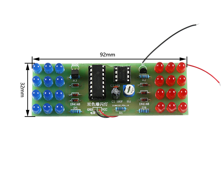
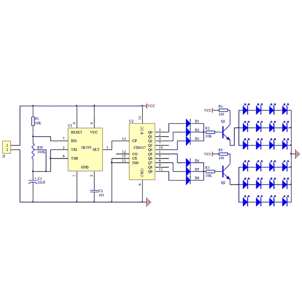
This kit uses NE555 and CD4017 chips to form an analog alarm light circuit. The blue LED and red LED flash alternately according to the pulse, and the flash frequency can be adjusted by adjusting RP1. The working voltage of the circuit is DC9-12V, and the kit does not include a power supply (battery). The kit is simple to produce, has obvious effects, and is highly interesting. It is suitable for practical assembly by electronics enthusiasts and vocational school students.
2.Parameter:
1>.Work Voltage:DC 12V
2>.Work Temperature:-25℃~85℃
3>.Work Humidity:5%~95%RH
4>.Size:92x32mm
3. Circuit:
4.Common problem:
1>.The positive and negative electrodes of the LED are soldered incorrectly, and the long leg positive electrode. Be careful not to burn the LED during soldering. One bad or faulty soldering may cause one column to be off.
2>.The triode does not pay attention to the direction, and should be positioned in the same position as the shape on the board.
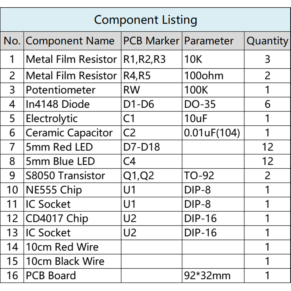
3>.The resistance value is incorrect. It is necessary to weld according to the resistance value on the board, with two being 100 ohms and three being 10K.
4>."The positive and negative electrodes of diode 1N4148 are wrong, with a black side as the negative electrode, and a horizontal bar on the board as the negative electrode.".
5>.The positive and negative electrodes of the electrolytic capacitor are incorrect, and the long leg is the positive electrode.
6>.The chip notch direction should be consistent with the notch direction on the board, as should the base.
7>.The power supply is connected reversely, causing the chip to burn out. The VCC is connected to the positive electrode, and the GND is connected to the negative electrode.


