- prev
- next
DIY AM FM Radio Kit, Am-FM 210SP Radio DIY Soldering Assembly Kits
$9.99
| Quantity | 5+ | 10+ | 30+ |
| Price | $6.70 | $6.30 | $5.75 |
Item ID: GY20514
Product Details
Description:
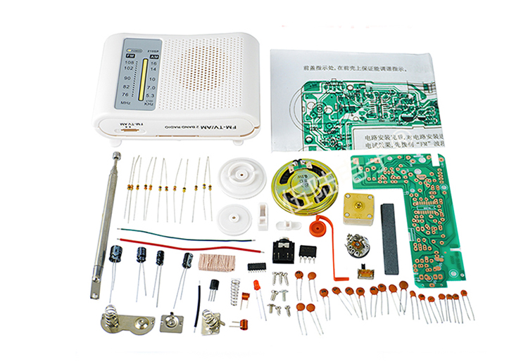
The CF210SP radio kit includes the circuit board, electronic parts, enclosure, speaker and antenna. Building it requires basic soldering experience and about 1-2 hours of your time.
This little radio is good for listening to news, podcasts and radio shows. Its output is limited,of course, due to the small speaker and the thin plastic enclosure.
It covers the AM and FM bands with 2 different ICs. One IC is a SMD component that is the heart of the FM tuner, and the other IC is a 2 pin IC that is the heart of the AM tuner. You can modify the receiver, do what ever you want with this kit. Please be careful and solder the SMD component very carefully right after soldering the passive components.
The FM tuner is like those DSP tuner chips, because it tunes and locks right on frequency when listening to the FM band, it has AM wide tuning, and it mostly picks up strong local AM stations and some distant ones like semi locals.
Feature:
EXQUISITE APPEARANCE DIY: This radio DIY kit is an AM/FM dual band radio with novel and unique appearance.
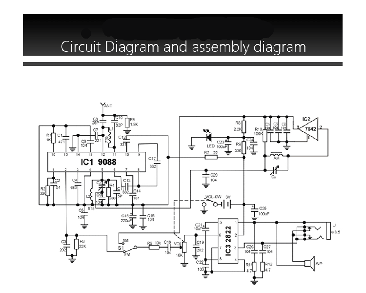
STABLE PERFORMANCE: The radio kit uses TDA2822 power amplifier circuit, which is a stereo audio amplifier chip to drive speakers and headphones. It’s not particularly fancy and is probably quiet hissy, and offers about 20mW into a set of 32 ohm headphones when powered from 3V. It is used to drive the headphone jack which disconnects the internal speaker once a headphone plug is plugged in.
RECEIVING RANGE: The frequency modulation band uses the CD9088 chip, the receiving frequency range is 76-108MHz; The TA7642 integrated direct amplifier circuit adopts the amplitude modulation band, the reception frequency range is 525-1605 kHz.
MULTI-FUNCTION: The electronic kit can not only receive FM radio, but also campus radio and some TV audio signals. Note: FM and AM reception are working parallel as soon the radio is turned on, and the AM/FM selector switch only selects the audio path to the amplifier.
Things You Need
No kit is entirely complete – there will be things you will need that don’t come in the kit. In the case of this kit, below are some of the things you may need to prepare:
About 1 to 2 hours of time to complete the kit.
A container of some sort to empty out the components and sort through them, so they don’t get lost.
An appropriate (~30-50w) soldering iron with a fine tip – the SMD chip absolutely demands it.
Some solder – 60/40 is the “good stuff”, lead free is not as fun.
Sidecutters to cut off component legs.
Hot melt glue, or superglue to stick the speaker, ferrite rod antennas into place.
Desoldering braid (optional) to fix mistakes.
Magnifying glass and light to read small component values and markings (also optional).
Small Philips head screwdriver to assemble the case and tuning/volume knobs.
Small flat-blade screwdriver to perform the variable-cap tuning procedure.
Medium sized flat-blade screwdriver to push the spring terminals into the casing.
Two AA batteries to power the receiver.
Bench-top supply with crocodile clips, 3V output to power receiver during tuning (recommended, but not absolutely necessary).
Another radio that is in tune to verify received stations (also recommended, but not absolutely necessary).
A multimeter of some sort, preferably with capacitance measurement ability and/or an LCR meter for troubleshooting and component identification.
Installation Guide:
Video Demo: