- prev
- next
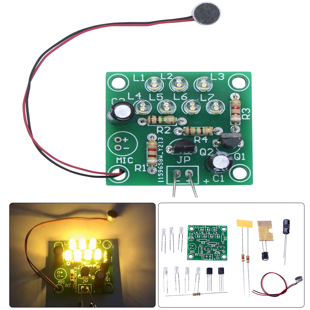
LED Rhythm Light DIY Kit Sound Control Music LED Flashing Melody Light Electronic Soldering Practice Kits
$4.19$5.9930%
| Quantity | 5+ | 10+ | 30+ |
| Price | $4.15 | $4.00 | $3.85 |
00d : 00h : 00m : 00s
Item ID: GY19483
Product Details
1.Description:
It is a sound control rhythm flashing light.
With the sound of music or other sounds,the LED lights flash and move in accordance with the rhythm of the sound (the speed of the sound).
After the welding is successful,you can feel the wonderful melody combination of sound and light.
2.Feature:
1) It uses high-quality double-sided spray tin PCB board,which is easy to solder.
2) It is equipped with a microphone with a line and supporting electronic components.
3) Its LED lights will light up with sound.
3.Parameter:
1) Product Name:Sound Control Rhythm Flashing Light
2) Working Voltage:DC 3V-6V
3) Number of Diodes:7pcs
4) Work Temperature:-25℃~85℃
5) Work Humidity:5%~95%RH
6) PCD Size:31*29*1.6mm
7) Size(Installed):31*29*20mm
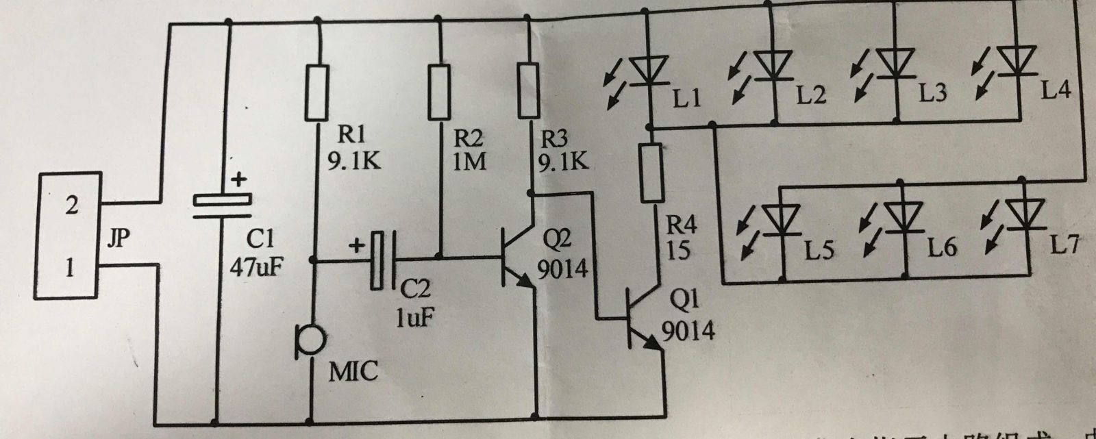
4.Circuit Principle:
1) The sound-controlled LED melody light circuit is composed of a power supply circuit,a microphone amplifier circuit,and an LED light-emitting indicator circuit.The power supply is input by JP,and C1 is filtered for use in the circuit.
2) The MIC converts the sound signal into an electric signal,which is coupled to Q2 through C2 and amplified,and the amplified signal is sent to the base of Q1.Q1 pushes the LED to emit light.The louder the sound,the higher the brightness of the LED.
5.Installation Tips:
1) There are positive and negative points for electret microphones.
The end connected to the aluminum shell is the negative end.
During installation,the two wires of the microphone can be soldered to the circuit board through the fixing holes through the circuit board,so that the wires are not easy to break.
2) The power supply has positive and negative differences.
Generally, DuPont cable is used to connect the power supply.
It can also be connected directly with a 3-6V battery box according to the situation.
3) The circuit adopts high-brightness concave electrodeless warm white-yellow dual-color LED.
This kind of LED can emit light in both positive and negative directions.
It emits warm white light in the forward direction and yellow light in the reverse direction.
All of them should be in the same direction when installed,otherwise the light may be uneven.
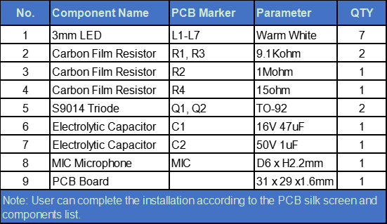
6.Installation Steps:
1.Install 1pcs 1Mohm resistor on R2
2.Install 1pcs 15ohm resistor on R4
3.Install 2pcs 9.1Kohm resistors on R1, R3
4.Install 7pcs of LEDs on L1-L7
5.Install 2pcs S9014 Triodes on Q1 and Q2
6.Install 16V 47uF Capacitor on C1
7.Install 50V 1uF Capacitor on C2
8.Install Microhone on MIC. Black line to negative pole - , red line to positive pole +
7. Components List