
- prev
- next
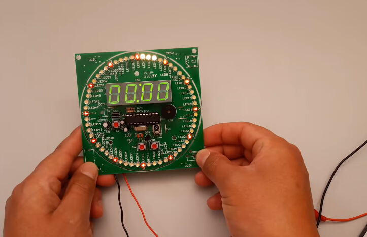
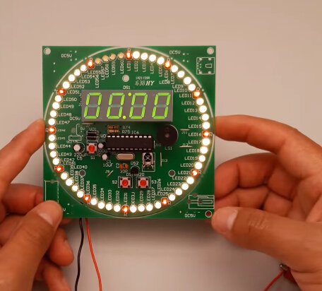
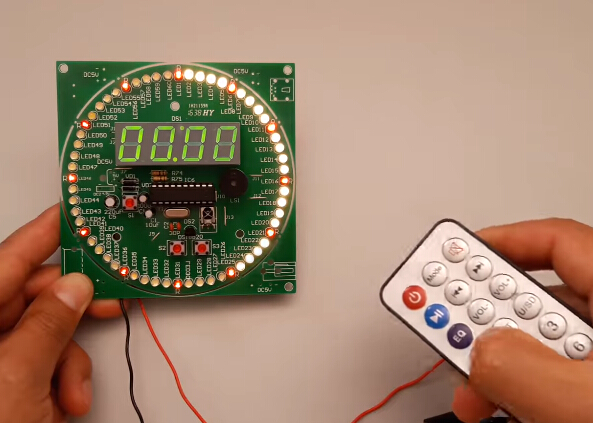
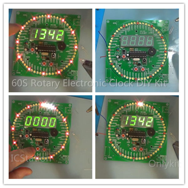
60S Rotary Electronic Clock DIY Kit 4 Digits Digital Clock Colorful Flashing LED Light DIY Kits with Remote Control
| Quantity | 3+ | 5+ | 10+ |
| Price | $8.20 | $7.99 | $7.80 |
Product Details
NOTE:
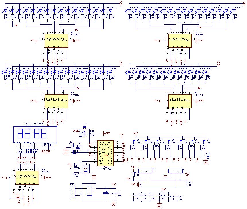
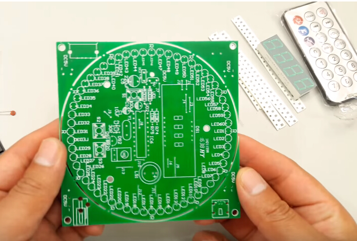
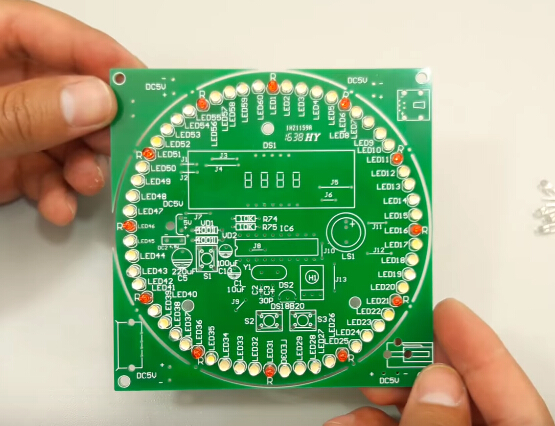
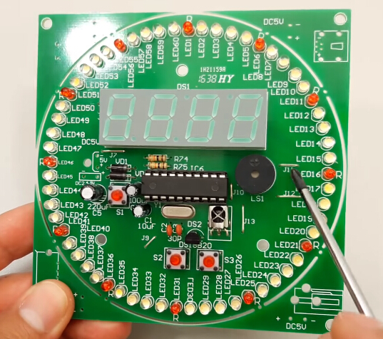
Component List:
|
Component |
Number |
Parameter |
Quantity |
|
Electrolytic capacitor |
C1 |
10uF |
1 |
|
Ceramic capacitor |
C2,C3 |
30pF |
2 |
|
0805 Capacitor |
C4,C6-C12 |
104 |
8 |
|
Electrolytic capacitor |
C5 |
220uF |
1 |
|
Electrolytic capacitor |
C13 |
100uF |
1 |
|
1*2P Male pin |
DC5V |
2.54mm |
1 |
|
4Bit digital tube |
DS1 |
|
1 |
|
74HC595 |
IC1-IC5 |
SOP-16 |
5 |
|
20P IC Socket |
IC6 |
|
1 |
|
STC11F04 |
|
DIP-20 |
1 |
|
3mm LED |
LED5,LED10,LED15,LED20, LED25,LED30,LED35,LED40, LED45,LED50,LED55,LED60 |
Red |
12 |
|
3mm LED |
|
White |
48 |
|
Buzzer |
LS1 |
|
1 |
|
S8550 |
Q1-Q7 |
SOT-23 |
7 |
|
0805 Resistor |
R1-R68 R80 |
470ohm |
69 |
|
0805 Resistor |
R69-R73,R76,R76,R77,R79 |
10K |
8 |
|
Metal film Resistor |
R74,R75 |
10K |
2 |
|
0805 Resistor |
R78 |
5.1K |
1 |
|
6*6*5 Button |
S1,S2,S3 |
|
3 |
|
HC-49S Crystal |
Y1 |
12MHz |
1 |
|
1N5819 |
VD1-2 |
|
1 |
|
PCB |
|
|
1 |
|
DS18B20 |
DS2 |
TO-92 |
1 |
|
IR receiver |
H1 |
HX1838 |
1 |
|
Infrared remote control |
|
|
1 |
Button S3: Function control buttons
|
Mode(Display on first 2 Bits) |
Function |
Debug(Display on 2Bits from right) |
Instruction |
|
01 |
Display and Correction seconds |
Correction seconds |
It can be used as a stopwatch |
|
02 |
Display and Correction minutes |
Correction minutes |
|
|
03 |
Display and Correction hours |
Correction hours |
|
|
04 |
Hourly timekeeping |
0:Timekeeping at 00:00-23:00 1:Timekeeping at 7:00-22:00 2:Close Timekeeping |
|
|
05 |
Adjust the time speed |
0-99 Position. Default 50 The higher the number, the faster time |
|
|
06 |
1-Channel Alarm Clock minutes adjustment |
Display and adjustment |
|
|
07 |
1-Channel Alarm Clock hours adjustment |
Display and adjustment |
|
|
08 |
2-Channel Alarm Clock minutes adjustment |
Display and adjustment |
|
|
09 |
2-Channel Alarm Clock hours adjustment |
Display and adjustment |
|
1. Tested by ICStation's Outstanding Partner Muy Fácil De Hacer:
Learn More Details in the Video:
2. Tested by ICStation's Outstanding Partner Onlykit:
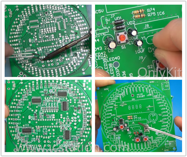
Learn More Details in the Video:
(The language is Russian)


