- prev
- next
DIY Rotating LED Light DIY Electronics Kit, LED Flashing Light Circuit Board Soldering Practice Kits
Product Details
1.Introduction:
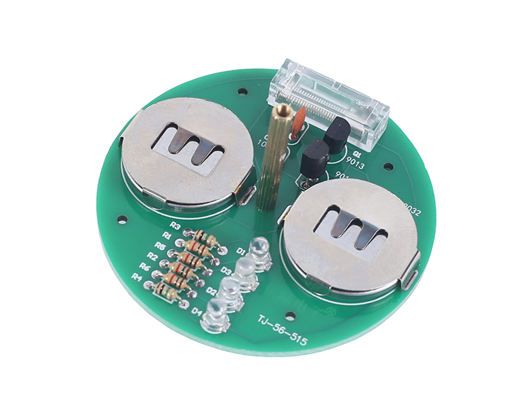
TJ-56-515 is an Desktop RGB LED Rotary Gyro Electronic Soldering DIY Kit. It is a multivibrator circuit composed of a transistor, which drives two groups of LED to flash alternately.
When rotating, the vibration switch is powered on, and the circuit starts to work. Because of the phenomenon of visual persistence, patterns appear one by one.It is a very interesting DIY electronic product which enables users to understand the circuit more clearly and learn soldering skills.
2.Parameter:
Product Name: TJ-56-515 Desktop RGB LED Rotary Gyro DIY Kit
Work Voltage:DC 6V
Color: Red/Green/Blue/Orange
Work Temperature:-40℃~85℃
Work Humidity:5%~95%RH
Size(Installed):52x52x35mm
3.Installation Manual (PDF, in English):
.png)
4.Video Demo:
5.Circuit Instruction:
When the battery is installed, the vibration switch S1 is disconnected, so the circuit does not work.
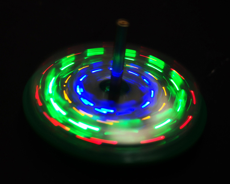
When rotating the spinning top, due to centrifugal left and right, the vibration switch S1 is turned on, and the circuit works.
The working principle of the multivibrator circuit is that when the power is turned on, the two transistors Q1 and Q2 will compete to be turned on first, but due to the difference of components, only one of the transistors will be turned on first.
Then the two transistors in the circuit are turned on and off in turn, and the two light-emitting diodes keep emitting light in cycles. When the top is rotated, a straight line will appear on the lit LED. Since the lamps are staggered and every two lamps are alternately lit, a pattern in the shape of a plurality of dotted lines appears.
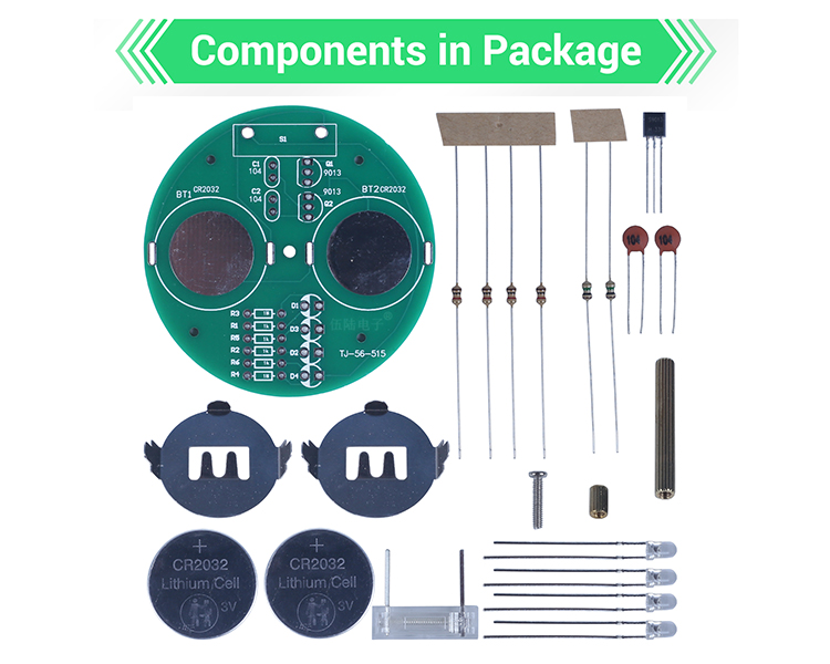
6.Components List:
.png)
CR2032 batteries included.