- prev
- next
Time Delay Relay Module Digital LCD Display 6-30V Control Timer Switch Trigger Cycle Module for Smart Control
Product Details
Description:
It is a multifunction delay relay module.LCD display, very clear, easy to use, powerful. It can be widely used at Smart home,Industrial control,Automatic irrigation,Indoor ventilation.Protection equipment.
✔. With LCD display, the current mode and parameters are clear at a glance, very clear and convenient. Wide voltage supply (6~30V), very practical to use.
✔. Support button trigger control, high and low level trigger, switch quantity control, suitable for most occasions.
✔. One-button pause function with reverse connection protection, reverse connection won’t cause burnout.
✔. Support UART data uploading and parameter setting. Different OP, CL, and LOP parameters can be set. These parameters are independent of each other and saved separately. And all setting parameters are automatically powered off and saved.
✔. Sleep mode added. The LCD backlight will be turned off automatically if there is no operation for about 5 minutes, then be woke up by pressing any button on the board.
Features:
1>. LCD display;
2>. Support high and low level trigger;
3>. Support button trigger;
4>. Emergency stop function;
5>. Sleep mode,Wake up with any button;
6>. Automatically save parameters;
7>. Support UART Set;
8>. Independent of parameters;
9>. With case, beautiful and practical;
10>. Support reverse connection protection;
11>. Delay high precision;
12>. Continuously adjustable from 0.01 seconds to 9999 minutes;
13>. Optocoupler isolation.Enhanced anti-jamming capability;
14>. Multiple parameters are displayed simultaneously.
Parameters:
1>. Product Name: Delay Relay Module
2>. Product Number: XY-WJ01
3>. Working Voltage: DC 6V-30V
4>. Control Load Current: 10A(Max)
5>. Quiescent Current: 15mA
6>. Working Current: 50mA
7>. Working temperature: -40~85℃
8>. Operating Humidity: 5%-99%RH
9>. Suitable for battery: Storage Battery, Lithium battery
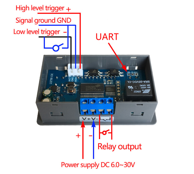
10>. Trigger signal source: High level trigger (3.0V~24V), Low level trigger (0.0V~0.2V), switching control (passive switch)
11>. Reverse Protection: Yes
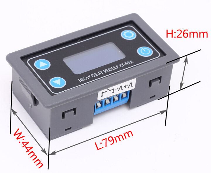
12>. Physical Dimension: 79*44*26mm
Function:
1>.Trigger delay.
Module will began to delay after get a trigger signal.And output terminal status will change after delay.This function can be used in circuit protect form misoperation or prevent instantaneous high current.
2>.Cycle timing.
The load switch changes state according to the specified time after set cycle time.
3>.Delayed power off.
If use need control a light that need it power off after some time.This module can meet this function.
4>.Circuit switch.
Protect the circuit from damage caused by prolonged operation.
Working mode:
P0:Relay will keep ON for time OP after get trigger signal and then relay OFF;The input signal is invalid if get trigger signal again during delay time OP.
P1:Relay will keep ON for time OP after get trigger signal and then relay OFF;Module will restart delay if get trigger signal again during delay time OP.
P2:Relay will keep ON for time OP after get trigger signal and then relay OFF;Module will reset and stop timing if get trigger signal again during delay time OP.
P3:Relay will keep OFF for time CL after get trigger signal and then relay keep ON.
P4:Relay will keep ON for time OP after get trigger signal and then relay keep OFF for time CL and then loops the above action.Module will reset and stop timing and relay will keep initial state if get trigger signal again during loops.The number of cycles (LOP) can be set.Relay will keep OFF if end loop.
P5:Relay will keep OFF for time CL after get trigger signal and then relay keep ON for time OP and then loops the above action.Module will reset and stop timing and relay will keep initial state if get trigger signal again during loops.The number of cycles (LOP) can be set.Relay will keep ON if end loop.
P6:Relay will keep ON for time OP after power on without get trigger signal and then relay keep OFF for time CL and then loops the above action.The number of cycles (LOP) can be set.Relay will keep OFF if end loop.
P7:Relay will keep OFF for time CL after power on without get trigger signal and then relay keep ON for time OP and then loops the above action.The number of cycles (LOP) can be set.Relay will keep ON if end loop.
P8:Signal hold function.Reset delay time and relay keep ON if keep get trigger signal.Relay OFF when the signal disappears after delay time OP.Reset delay time when get trigger signal again during timing.
P9:Signal hold function.Reset delay time and relay keep OFF if keep get trigger signal.Relay ON when the signal disappears after delay time CL.Reset delay time when get trigger signal again during timing
P0~P7 mode:System will start to delay if short press button ‘Pause’ when system does not get trigger signal.Display screen will display ‘OUT’ and flashing and Relay OFF when Pause timing if the system has been timed.
P8~P9 mode:Other buttons cannot be used when ‘Pause’ button as a trigger signal in running interface.
Timing Range:
Continuously adjustable from 0.01 seconds to 9999 minutes.
Enter the settings interface when short press button ‘Pause’ in the OP / CL parameter modification interface(Flashing) to select timing range.
Pay attention to the position where the decimal point moves when the button is pressed.
Display ‘XXXX’. No decimal point, the timing range is 1 second ~ 9999 seconds.
Display ‘XXX.X’. The decimal point is the penultimate, timing range is 0.1 second to 999.9 seconds.
Display ‘XX.XX’. The decimal point is the third last, timing range is 0.01 second to 99.99 seconds.
Display ‘X.X.X.X’. The decimal point is fully lit, timing range is 1 minute to 9999 minutes.
For example, if you want to set the OP to 3.2 seconds, move the decimal point to the penultimate position, LCD will display ‘003.2’.
Parameter Description:
OP: Turn On time;
CL: Turn OFF time;
LOP: Number of cycles.Range is 1-9999tims.’----’ means unlimited loop.
Set Parameter:
Long press:keep press button for more than 3second.
1>. Enter set parameter menu by long press button 'SET'.
2>. Work mode will flash at first set the working mode.Short press the UP/DOWN button to set the working mode.
3>. Short press the SET button to select the working mode and enter the system parameter settings.
4>. In the system parameter setting interface, short press the ‘SET’ button to switch the system parameters to be modified, short/long press the UP/DOWN button to modify value;
Note:Short press ‘SET ’ is invalid at mode P0,P1,P2,P3,P7,P8.
5>. Enter setting interface when short press button ‘Pause’ in the OP/CL parameter modification interface(Flashing) to select timing range (1s/0.1s/0.01s/1min).
6>. Save the parameter settings and exit the settings interface when long press ‘SET’ button after all the parameters are set.
Additional Features:
1>.Auto sleep function: Long press button 'Pause' in the normal running interface(P0~P7) to turn on or off auto sleep function.
L-P:ON,Turn ON auto sleep function.About five minutes, no operation, the LCD backlight automatically turns off.It can be wake up by any buttons.
L-P:OFF,Turn OFF auto sleep function.
2>.View parameters: In the running interface, short press the SET button to display the current parameter settings of the system, which does not affect the normal operation of the system.
3>.Switch the display parameter: It will switch the display content by short press button 'DOWN' in the P5~P6 mode(Parameter is Run time or number of cycles)
UART Communication and Parameter Settings:
The system supports UART data upload and parameter setting functions (TTL level);
UART: 9600, 8, 1
| NO. | Command | Function |
| 1 | Read | Read the parameter setting |
| 2 | OP:XXXX | Set the minimum delay time for turn ON : 1s |
| 3 | OP:XXX.X | Set the minimum delay time for turn ON : 0.1s |
| 4 | OP:XX.XX | Set the minimum delay time for turn ON : 0.01s |
| 5 | OP:X.X.X.X | Set the minimum delay time for turn ON : 1min |
| 6 | CL:XXXX | Set the minimum delay time for turn OFF : 1s |
| 7 | CL:XXX.X | Set the minimum delay time for turn OFF : 0.1s |
| 8 | CL:XX.XX | Set the minimum delay time for turn OFF : 0.01s |
| 9 | CL:X.X.X.X | Set the minimum delay time for turn OFF : 1min |
| 10 | LP:XXXX | Number of cycles:1-9999 |
| 11 | Start | Trigger/Start(Just for P0~P7) |
| 12 | Stop | Pause(Just for P0~P7) |
| 13 | PX | Set mode P0~P9 |
Application:
1>. Motor
2>. Robot
3>. Smart home
4>. Industrial control
5>. Automatic irrigation
6>. Indoor ventilation
Note:
1>. It is a relay output mode and cannot be used as a power module. It cannot output voltage. The load needs to be connected to a separate power supply.
Package:
1>.1pcs XY-WJ01 Delay Relay Module;
Button Function:
.jpg)
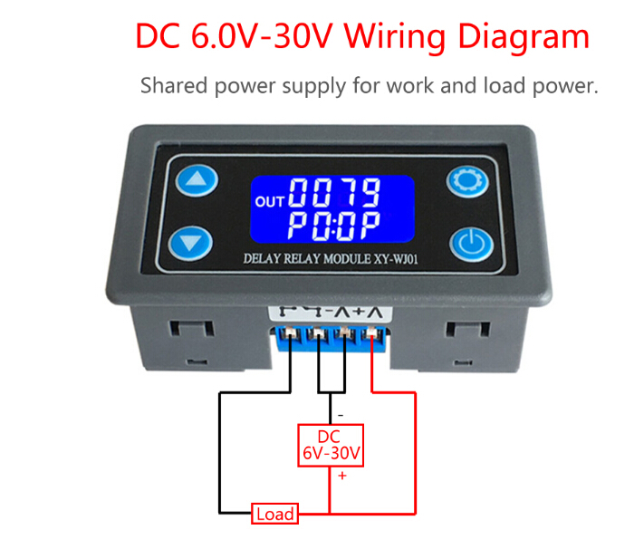
DC 6V-30V Wiring Diagram:
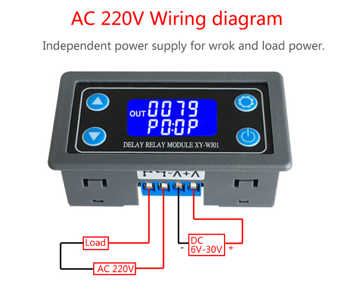
AC 220V Wiring Diagram:
Pin Definition:
Size: