
- prev
- next
DIY Kit Voice Control Lamp LED Melody Light DIY Electronic Kits
| Quantity | 3+ | 5+ | 10+ |
| Price | $2.05 | $1.99 | $1.75 |
Product Details
1.Description:
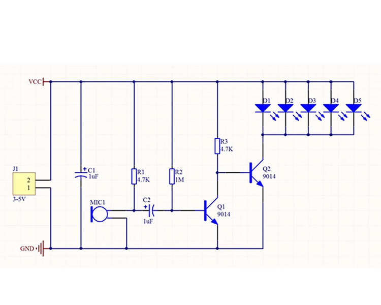
The voice controlled LED melody light circuit consists of a power supply circuit, a microphone amplification circuit, and an LED light emitting indicator circuit. The power supply is input by J1, and C1 filtering is used for the circuit.
After the kit is successfully produced, as music or other sounds sound, the five LED lights flash and move with the rhythm of the sound (the speed of the sound). Can be placed near the sound system, you can feel the wonderful melody combination of sound and light, and let the light dance with the music!
2. Feature:
The louder the sound, the brighter the LED
A small and cheap kit to practice your soldering skills and learn basic electronics knowledge and troubleshooting a circuit.
This Soldering Practice Kit is simple, suitable for children and electronic beginners to practice soldering. A good father-son time diy project at home.
3.Parameter:
1>.Work Voltage:DC 3-5.5V
2>.Work Temperature:-25℃~85℃
3>.Work Humidity:5%~95%RH
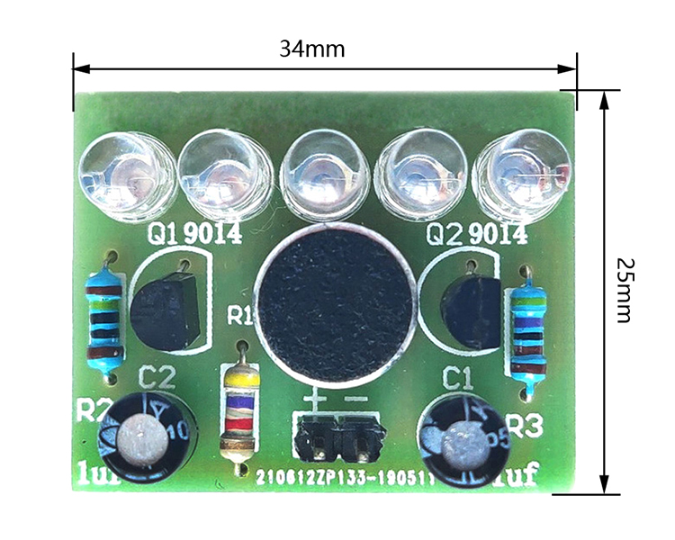
4>.Size:34x25mm
3.Common problem:
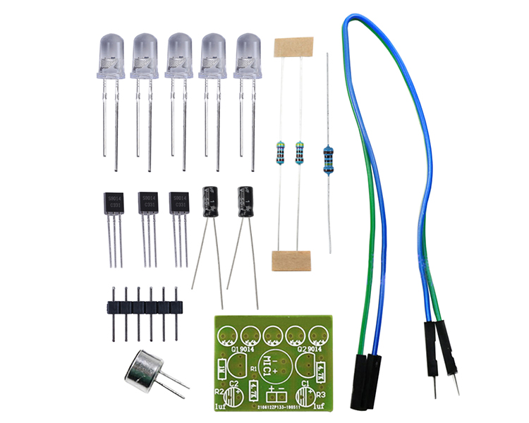
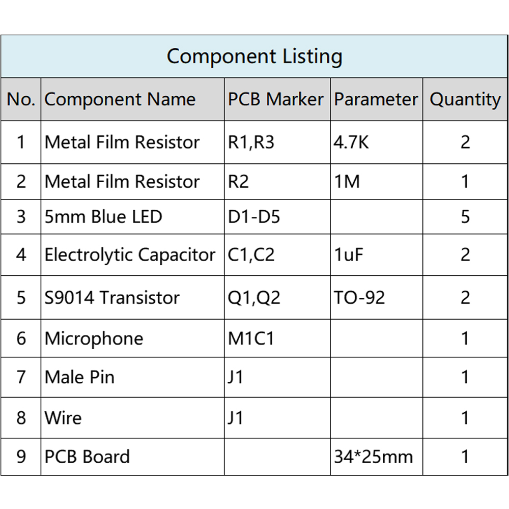
1>.The positive and negative electrodes of the LED are not noticed, and the long leg is the positive electrode.
2>.If the three resistors are not welded according to the identification on the board, use a multimeter to measure or read the resistance color ring.
3>.The triode was not inserted according to the shape on the board, resulting in incorrect orientation.
4>.The positive and negative electrodes of the microphone are not aligned, and the long pin positive electrode or the pin connected to the housing is the negative electrode.
5>.The capacitance of electrolytic capacitor is soldered incorrectly, one is 1uf, and the other is 47uf. Pay attention to distinguishing between them. Long pin positive electrode.
6>.The positive and negative electrodes of the power supply are connected reversely, subject to the identification on the board. The line corresponding to the+sign is the positive electrode, and the line corresponding to the - sign is the negative electrode.
7>.Check for welding short circuits and faulty soldering. The power supply voltage is 3-5.5V, and a stable power supply is required. It is best to use batteries for power supply.


