- prev
- next
DIY Kit Sound Light Controller LED Delay Light Voice Controlled Melody Light Audio Indicator
$2.79$3.9930%
| Quantity | 10+ | 30+ | 50+ |
| Price | $2.70 | $2.60 | $2.50 |
00d : 00h : 00m : 00s
Item ID: GY17435
Product Details
DIY Kit Sound Light Controller LED Delay Light Voice Controlled Melody Light
Let us see 2 videos first:)
1.Introduction:
SCL-8 is a sound light controller. Its LEDs can be controlled by sound and photoresistor sensor and switch control status by self-locking switch.
2.Parameter:
1>.Model:SCL-8
2>.Work Voltage:DC 5V
3>.Work Current:130mA
4>.Delay time:About 10second
5>.Work Mode:Sound Control and Light Control
6>.Work Temperature:-40℃~85℃
7>.Work Humidity:0%~95%RH
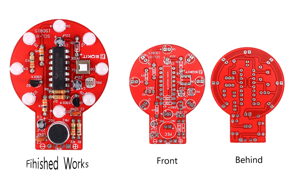
8>.Size(Installed):60*45*12mm
3.Work Mode:
1>.Sound Control LED Lamp:
1.1>.8pcs LED will turn ON if there is sound near the microphone.
1.2>.This function can work normally without affected by light.
1.3>.It needs press ON self-locking switch.
2>.Light Control Delay LED Lamp:
2.1>.8pcs LED will turn ON if there is sound near the microphone in a dark environment. And then turn OFF after about 10second.
2.2>.It can not work in a bright environment.
2.3>.It needs release self-locking switch.
2.4>.Note:the delay time can not be adjustable.
4.Installation Tips:
1>.User needs to prepare the welding tool at first.
2>.Please be patient until the installation is complete.
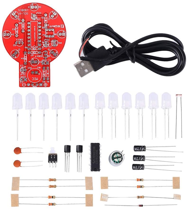
3>.The package is DIY kit.It need finish install by user.
4>.The soldering iron can't touch the components for a long time(1.0 second), otherwise it will damage the components.
5>.Pay attention to the positive and negative of the components.
6>.Strictly prohibit short circuit.
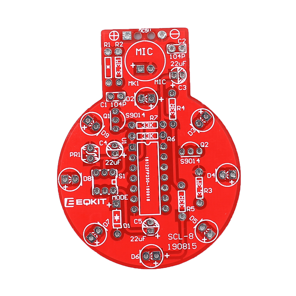
7>.Users can complete installation by PCB silk screen and component listing.
8>.User must install the LED according to the specified rules.Otherwise some LED will not light.
9>.Install complex components preferentially.
10>.Make sure all components are in right direction and right place.
11>.It is strongly recommended to read the installation manual before starting installation.
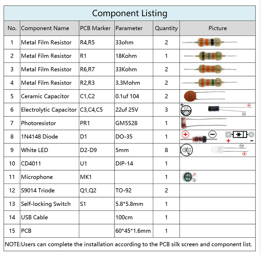
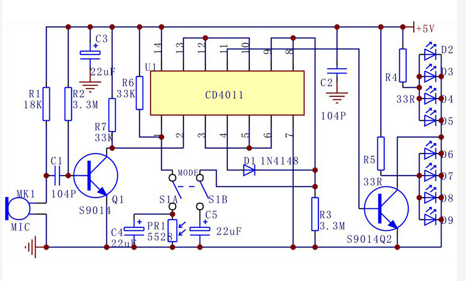
5.Installation Steps:
Step 1: Install 2pcs 33ohm metal film resistor at R4 and R5.
Step 2: Install 1pcs 18Kohm metal film resistor at R1.
Step 3: Install 2pcs 33Kohm metal film resistor at R6 and R7.
Step 4: Install 2pcs 3.3Mohm metal film resistor at R2 and R3.
Step 5: Install 1pcs DO-35 1N4148 diode at D1.Pay attention to the positive and negative of the component.
Step 6: Install 2pcs 0.1uf 104 ceramic capacitor at C1 and C2.
Step 7: Install 1pcs GM5528 photoresistor sensor at PR1.
Step 8: Install 2pcs TO-92 S9014 triode at Q1 and Q2.
Step 9 Install 1pcs Microphone at MK1.Pay attention to the positive and negative of the component.
Step 10: Install 3pcs 22uf 25V electrolytic capacitor at C3,C4,C5.Pay attention to the positive and negative of the components.The longer pin is positive pin.
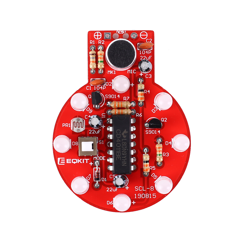
Step 11: Install 8pcs 5mm White LED at D2~D9.Pay attention to the positive and negative of the components.The longer pin is positive pin.
Step 12: Install 1pcs DIP-14 CD4011 at U1.Pay attention to the installation direction.
Step 13: Install 1pcs 5.8*5.8mm self-locking switch at S1.Pay attention to the installation direction.
Step 14: Install 1pcs USB as input work voltage.
Step 15: Test and Application.
.jpg)