
- prev
- next
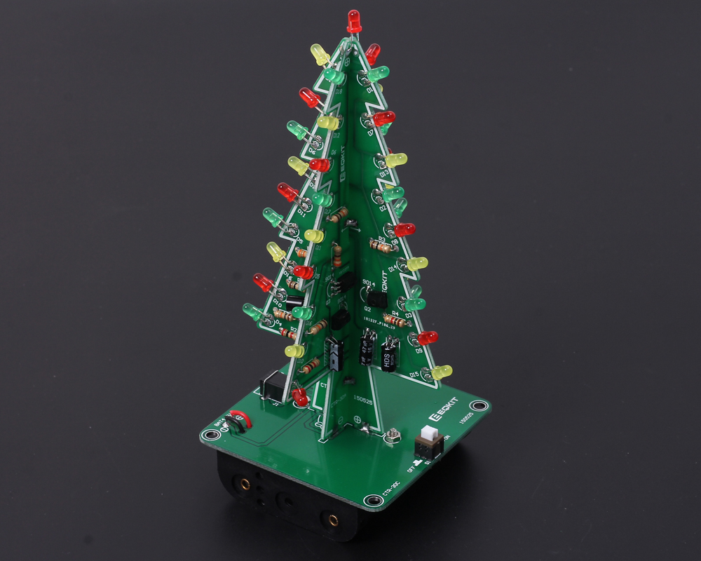
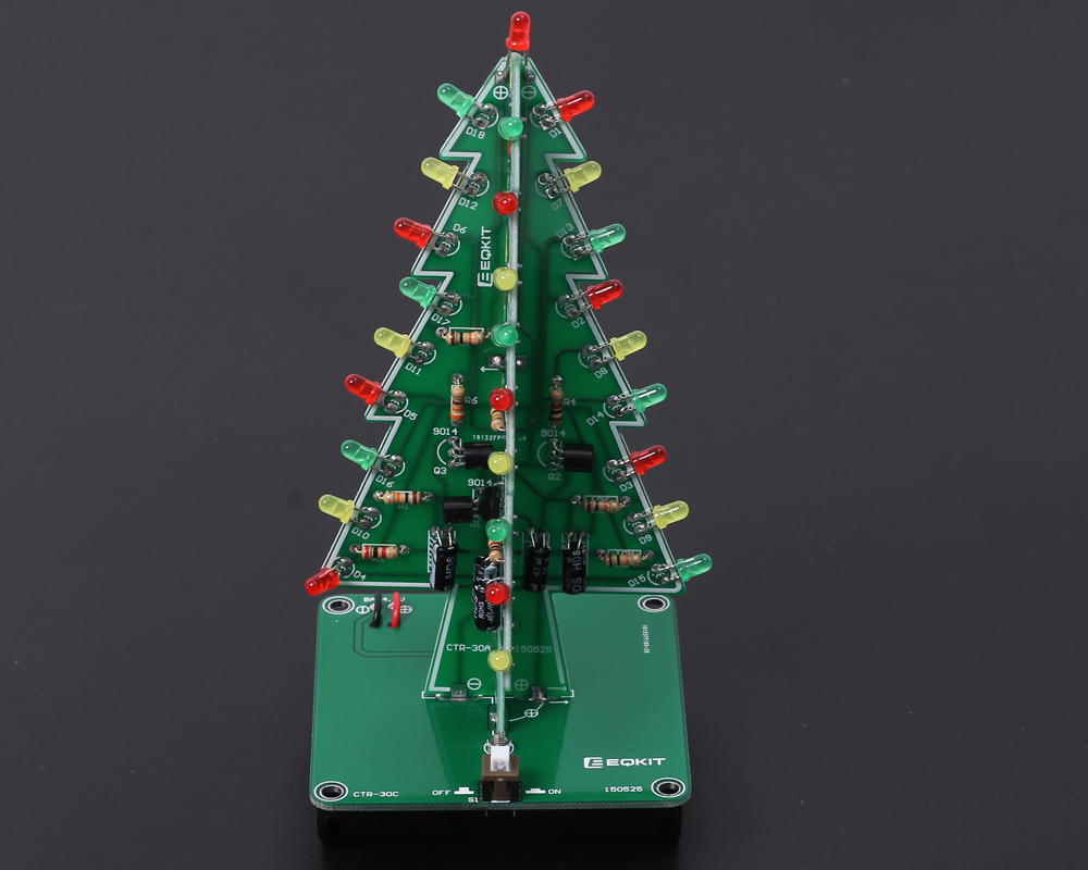
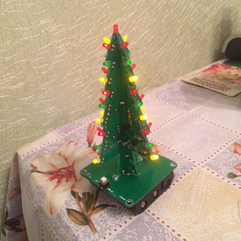
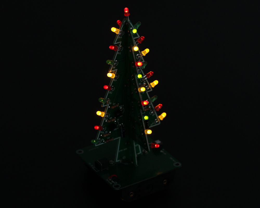
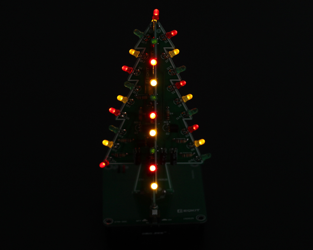
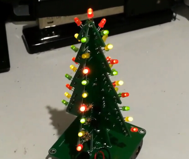
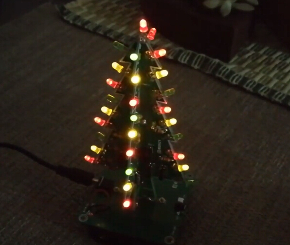
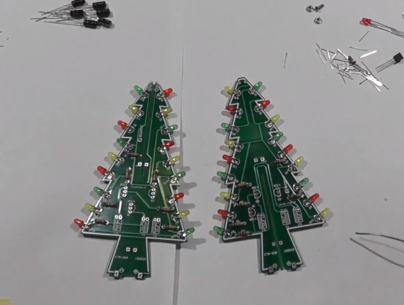
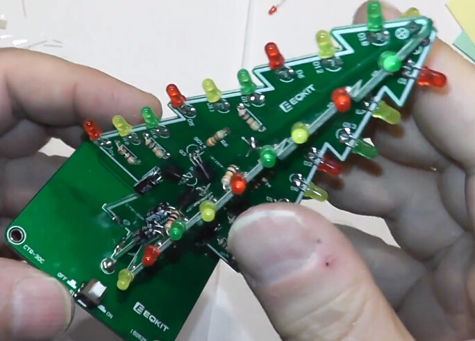
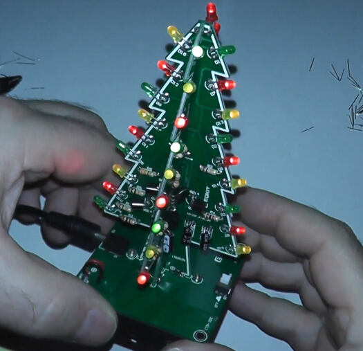
DIY Kit 3D Christmas Tree Kit with 3 Colors Red/Green/Yellow Flashing LED for Electronics Soldering Practice Xmas Fun Gift DC 5V
| Quantity | 5+ | 10+ | 20+ | 30+ | 50+ |
| Price | $5.30 | $5.10 | $4.80 | $4.50 | $4.20 |
Product videos
Reviewed by ICStation's Customer djquaky:
Product Details
| NO. | Parameter | Value |
| 1 | Model | CTR-30C |
| 2 | Work Voltage | DC4.5-5V |
| 3 | Power Type | AA*3 battery or USB Cable |
| 4 | Installation Size | 60mm*136mm*60mm |
| NO. | Component Name | PCB Marker | Parameter | QTY |
| CTR-30A | ||||
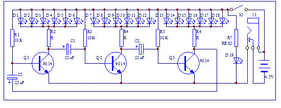
| 1 | Metal Film Resistor | R6 | 330ohm | 1 |
| 2 | Metal Film Resistor | R4 | 1K | 1 |
| 3 | Metal Film Resistor | R2 | 2K | 1 |
| 4 | Metal Film Resistor | R1,R3,R5,R7 | 10K | 4 |
| 5 | Electrolytic Capacitor | C1-C3 | 47uF 16V | 3 |
| 6 | Red LED | D1-D6,D19 | 3mm | 7 |
| 7 | Yellow LED | D7-D12 | 3mm | 6 |
| 8 | Green LED | D13-D18 | 3mm | 6 |
| 9 | S9014 Transistor | Q1-Q3 | TO-92 | 3 |
| 10 | PCB | CTR-30A | 1 | |
| CTR-30B | ||||
| 11 | Metal Film Resistor | R6 | 1K | 1 |
| 12 | Metal Film Resistor | R4 | 2K | 1 |
| 13 | Metal Film Resistor | R2 | 330ohm | 1 |
| 14 | Metal Film Resistor | R1,R3,R5 | 10K | 3 |
| 15 | Electrolytic Capacitor | C1-C3 | 47uF 16V | 3 |
| 16 | Green | D1-D6 | 3mm | 6 |
| 17 | Yellow | D7-D12 | 3mm | 6 |
| 18 | Red | D13-D18 | 3mm | 6 |
| 19 | S9014 Transistor | Q1-Q3 | TO-92 | 3 |
| 20 | PCB | CTR-30B | 1 | |
| CTR-30C | ||||
| 21 | Self-Locking Switch | S1 | 5.8mm | 1 |
| 22 | DC Power Socket | J1 | 3.5mm | 1 |
| 23 | Battery Box | AA*3 | 1 | |
| 24 | USB to DC 3.5mm Cable | 80cm | 1 | |
| 25 | Screw | M2*8mm | 2 | |
| 26 | Nut | M2 | 2 | |
| 27 | PCB | CTR-30C | 1 | |

1>. 1pcs 330ohm Metal Film Resistor
2>. 1pcs 1K Metal Film Resistor
3>. 1pcs 2K Metal Film Resistor
4>. 4pcs 10K Metal Film Resistor
5>. 3pcs 47uF 16V Electrolytic Capacitor
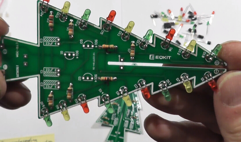
6>. 7pcs 3mm Red LED
7>. 6pcs 3mm Yellow LED
8>. 6pcs 3mm Green LED
9>. 3pcs S9014 Transistor
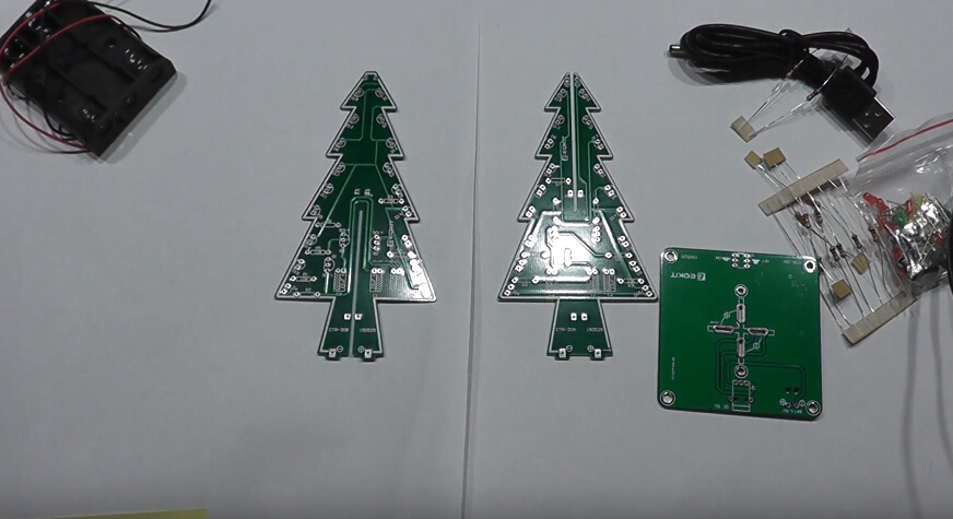
10>. 1pcs PCB CTR-30A
11>. 1pcs 330ohm Metal Film Resistor
12>. 1pcs 1K Metal Film Resistor
13>. 1pcs 2K Metal Film Resistor
14>. 3pcs 10K Metal Film Resistor
15>. 3pcs 47uF 16V Electrolytic Capacitor
16>. 6pcs 3mm Green LED
17>. 6pcs 3mm Yellow LED
18>. 6pcs 3mm Red LED
19>. 3pcs S9014 Transistor
20>. 1pcs PCB CTR-30B
21>. 1pcs Self-Locking Switch
22>. 1pcs 3.5mm DC Power Socket
23>. 1pcs AA*3 Battery Box
24>. 1pcs USB to DC 3.5mm Cable
25>. 2pcs Screw M2*8mm
26>. 2pcs Nut M2
27>. 1pcs PCB CTR-30C
6. Download the Installation Steps Here!

II. Tested by ICStation's Outstanding Partner DrakerDG:
Learn More Details in the Video:
(The language in the video is English)
III. Tested by ICStation's Outstanding Partner Berred:
Customer Reviews (2)
-
By John Smith2020-12-13 08:10:39
To follow up on my previous comment, R2 and R6 on. CTR-30B should be swapped. R6 should be a 2K ohm resistor and R2 should be the 330 ohm resistor. -
By John Smith2020-12-13 07:44:46
This is a fun little holiday project for someone with average soldering skills. It will take a little longer than you expect, but the result is good. One issue I'm having is that the green LEDs on CTR-30B are very faint compared to CTR-30A. I cannot figure out why this is, but when I check the video associated with this product, it looks like the same green LEDs are faint in the video as well. For that reason, I believe there might be an issue with the circuit. Perhaps the resistor values are incorrect. That said, the project still came out well.


