- prev
- next
Dual Channel Signal Generator 1Hz-160KHz PWM Frequency Duty Cycle Complimentary Adjustable Module LED Display
| Quantity | 3+ | 5+ | 10+ |
| Price | $4.70 | $4.30 | $3.90 |
Product Details
Description:
PWM signal generator is a device that provides electrical signals at a variety of frequencies, square wave, and output levels.It is used as a signal source or excitation source for testing.Widely used in production practice and technology.
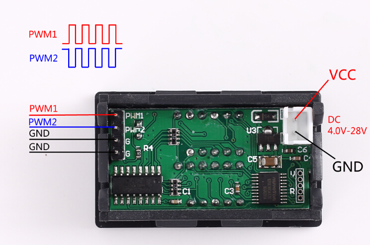
Dual PWM complementary output.They have the same frequency but complementary duty cycles.E.g. PWM1 duty cycle is 40%,then the duty cycle of PMW2 is 60%.
Features:
1>. With outer casing;
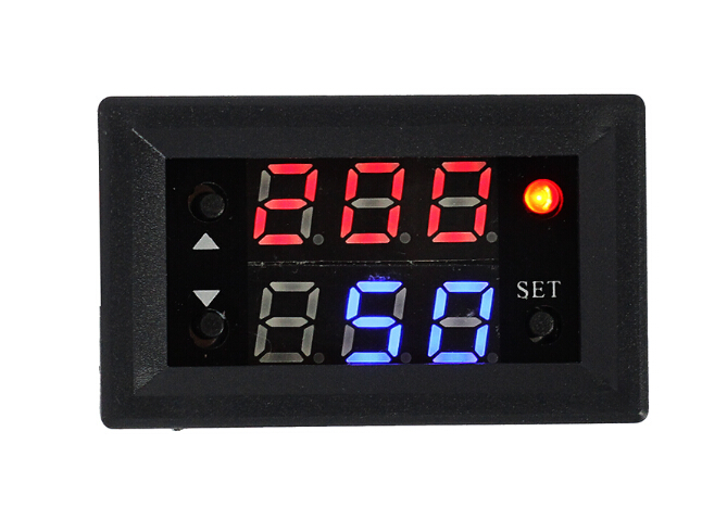
2>. LED display;
3>. Support frequency adjustment;
4>. Support duty cycle adjustment;
5>. High precision detection;
6>. Support power-down memory function;
7>. 2-Channel PWM output;
8>. Dual PWM complementary output.
Parameters:
1>. Product name: Dual Complementary PWM Signal Generator;
2>. Work voltage:DC 4.0V-30V;
3>. Frequency range:1Hz~160KHz;
4>. Frequency accuracy:2%;
5>. Duty cycle range:0.00%-100%;
6>. Output Current:About 5-30mA;
7>. Output amplitude:Same to input voltage;
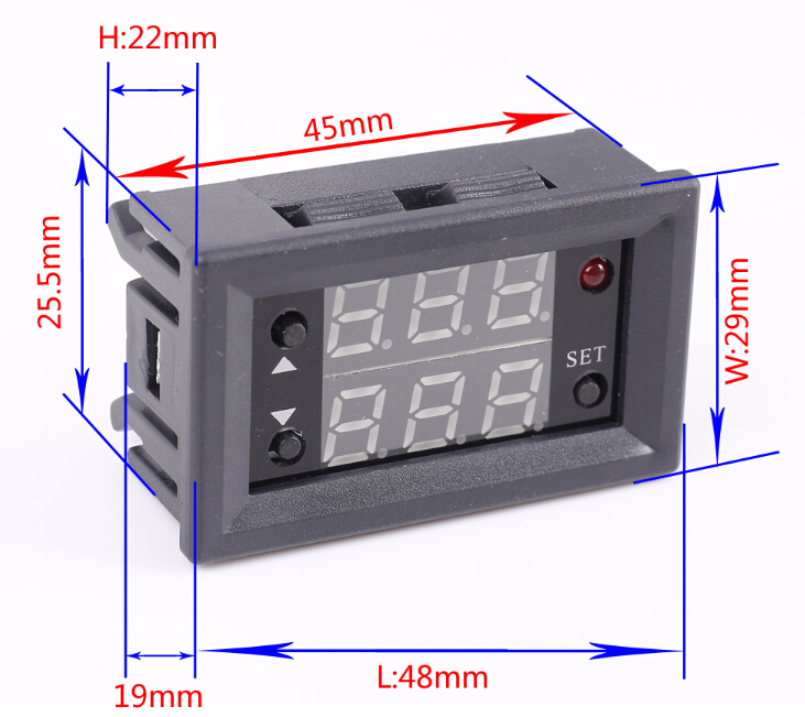
8>. Size for display:48*29*22mm;
9>. Operating temperature:-20℃~70℃;
Frequency set range:
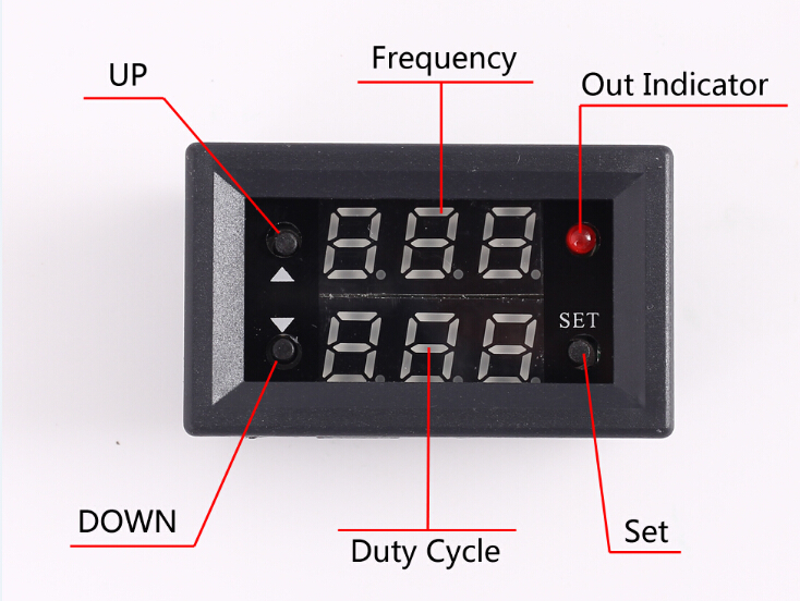
Enter the settings interface when short press button ‘SET’ in the normal running status to select frequency range.Automatically switch frequency range.(Display will auto flashing.The first line is frequency;The second line is duty cycle)
Pay attention to the position where the decimal point moves when the button is pressed.
Display ‘XXX’.No decimal point,The minimum frequency is 1Hz.The frequency range is 1Hz ~ 999Hz.
Display ‘X.XX’.The decimal point is the penultimate, The minimum frequency is 0.01KHz.The frequency range is 1.00KHz ~ 9.99KHz.
Display ‘XX.X’.The decimal point is the third last,The minimum frequency is 0.1KHz.The frequency range is 10.0KHz ~ 99.9KHz.
Display ‘X.X.X’.The decimal point is fully lit,The minimum frequency is 1KHz.The frequency range is 1KHz ~ 160KHz.
For example:
Display ‘109’ means PWM output frequency is 109Hz;
Display ‘1.39’ means PWM output frequency is 1.39KHz;
Display ‘27.3’ means PWM output frequency is 27.3KHz;
Display ‘1.3.4’ means PWM output frequency is 134KHz;
Duty Cycle Set Range:
Enter the settings interface when short press button ‘SET’ in the normal running status to select duty cycle.
Duty cycle range is 0.00%-100%.
The duty cycle that has been set is for PWM1.
For example:
If the duty cycle of the PWM1 is 40%, then the duty cycle of PMW2 is 60%.
Using Steps:
1>.Connect to power supply;
2>.Short press button ‘SET’ to set frequency or duty cycle;
3>.Short or long press button ‘UP’ or ‘DOWN’ to modify frequency or duty cycle;
4>.Automatically flashes for 6 seconds, parameters are automatically saved.;
5>.Connect to load.
Application:
1>.Square wave signal generator, generating square wave signal for experimental development;
2>.Used to generate a square wave signal that controls the motor driver;
3>.Generate adjustable pulses for use by the MCU;
4>.Dimmer;
5>.Speed governor;
Note:
It’s 2-channel PWM output signals from PWM1 and PWM2.
Package:
1>. 1pcs PWM Signal Generator;
2>. 1pcs 15cm 2P XH2.54-2P Cable;
3>. 4pcs 10cm DuPont line male to male;
Product Details:
Picture One:
Picture Two:
Picture Three:
Picture Four: