
- prev
- next
DIY Kit Electronic Windmill Shaped Red LED Flashing Light Lamp DC 5V Funny Kits for Soldering Practice
| Quantity | 10+ | 30+ | 50+ |
| Price | $2.90 | $2.60 | $2.30 |
Product Details
Description:
This is a DIY MCU design teaching Electronic windmills kit for soldering practice.
Parameters:
1>. Operating voltage: 5V
2>. Work efficiency: adjustable speed
3>. PCB board material: RF--4 high quality circuit board
4>. Size: 40mm*50mm
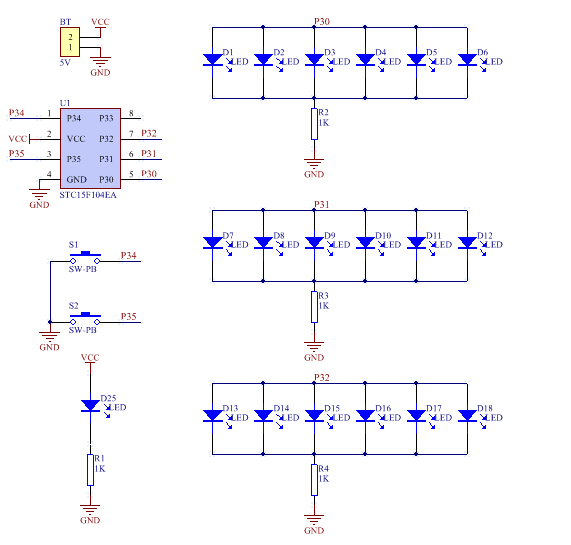
Circuit Principle:
- The circuit is based on MCU control.
- MCU control different vertical LED lighting, so as to achieve the effect of windmill rotation.
- The speed of the windmill can be changed by press the buttons.
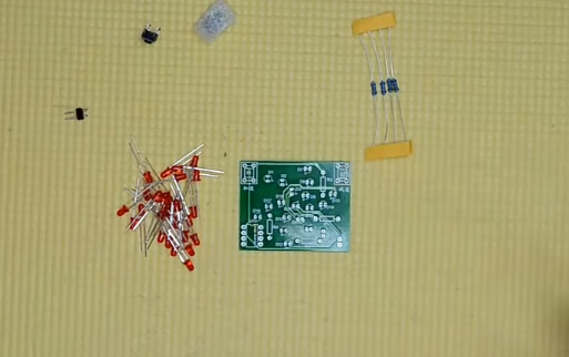
Component List:
| NO. | Component Name | PCB Marker | Parameter | QTY |
| 1 | Red LED | D1-D19 | 3mm | 19 |
| 2 | Metal Film Resistor | R1-R4 | 1K | 4 |
| 3 | Button | S1,S2 | 6*6mm | 2 |
| 4 | STC15F104EA | U1 | DIP-8 | 1 |
| 5 | Male Pin | DC | 2P | 1 |
| 6 | PCB | 40*50mm | 1 |
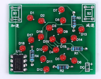
Circuit Diagram:
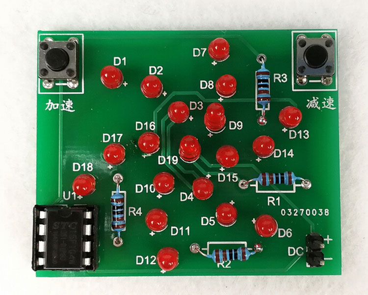
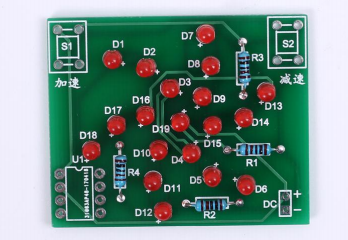
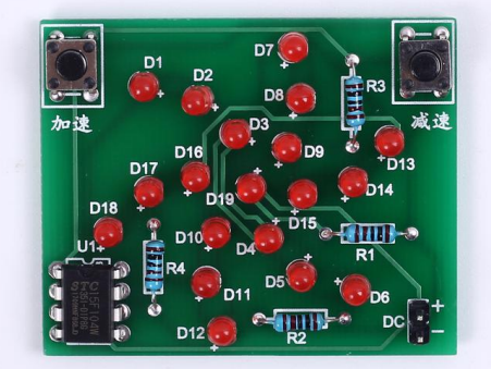
Finished Product Picture:
Installation Steps:
.png )
Step 1: Install the 4pcs 1K resistor
Step 2: Install all the 19pcs LEDs
Step 3: Install the IC chip
Step 4: Install the buttons and power interface
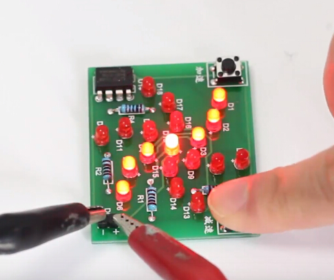
I. Tested by ICStation:
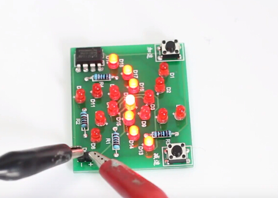
Press the accelerate button:
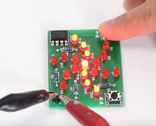
Press the decelerate button:
Learn More Details in the Video:
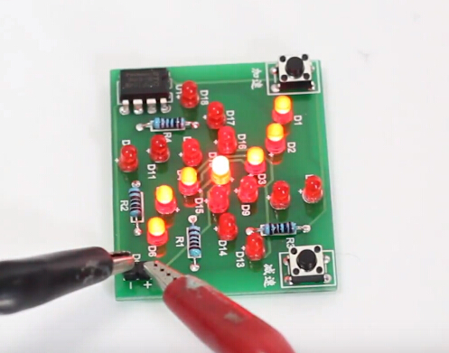
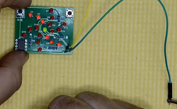
II. Tested by ICStation's Outstanding Partner ELECTROJUANYU:
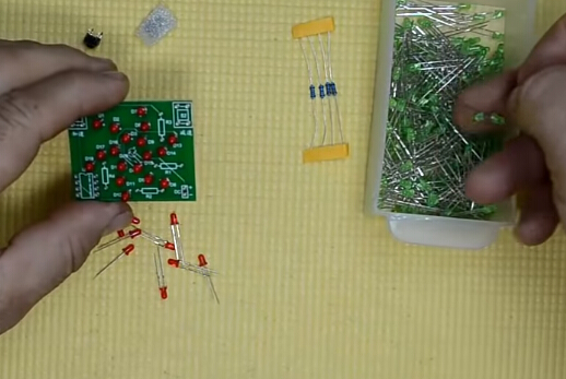
In order to observe easily, partner use a green LED assembling in the middle of the PCB board. :)


Learn More Details in the Video:
(The language in the video is Spanish)


