
- prev
- next
DIY Kit Red Green Flash LED Circuit DC 9V Christmas Trees LED Kit Electronic Soldering Learning Kit
| Quantity | 3+ | 5+ | 10+ | 50+ |
| Price | $3.60 | $3.50 | $3.30 | $2.50 |
Product videos
Product Details
1.Introduction:
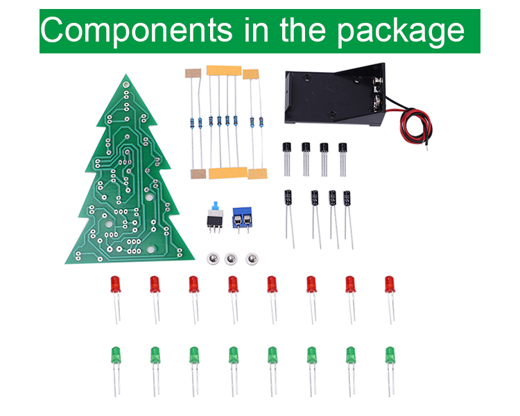
It is a flash led Christmas tree kit consists of circuit board, allows 16 LED flash alternately, showing a Christmas tree in the space of two-dimensional profile (the night environment has better viewing).
2.Feature:
16pcs highlight LED.
Simple circuit.
Automatic flashing.
Comes with 9V battery box.
3.Parameter:
1>.Work Voltage:DC 9V
2>.Work Current:100mA
3>.Power Type:Battery Box
4>.Work Module:Switch Control
5>.Color:Red+Green LED
6>.Work Temperature:-40℃~85℃
7>.Work Humidity:0%~95%RH
8>.Size(Installed):110*80*35mm
9>.Package: Pack of 1 Set (Battery doesn't included)
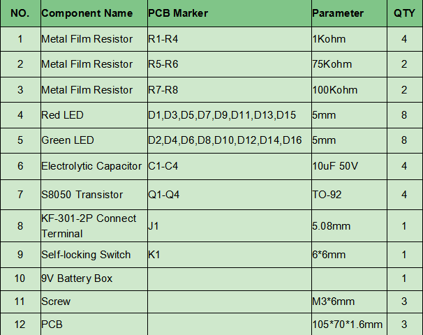
4.Component List:
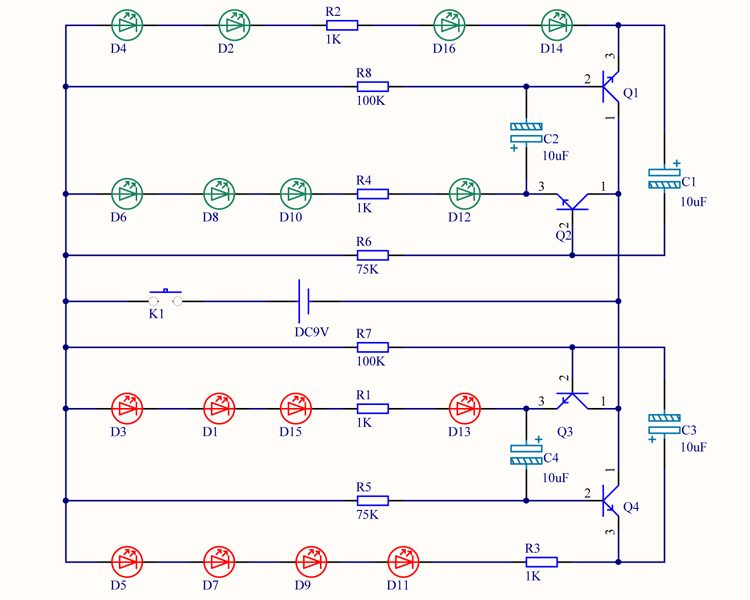
5.Schematic:
6.Installation Steps (Please be patient ):
Step 1: Install 4pcs 1Kohm Metal Film Resistor at R1-R4.
Step 2: Install 2pcs 75Kohm Metal Film Resistor at R5-R6.
Step 3: Install 2pcs 100Kohm Metal Film Resistor at R7-R8.
Step 4: Identification LED.The Longer pin is positive pole.The longer pin is inserted into the pad which has marked ‘ + ’.
Step 5: Install 8pcs 5mm Red LED at D1,D3,D5,D7,D9,D11,D13,D15.Bend the LED at the same time.
Step 6: Install 8pcs 5mm Green LED at D2,D4,D6,D8,D10,D12,D14,D16.Bend the LED at the same time.
Step 7: Install 4pcs TO-92 S8050 Transistor at Q1-Q4.
Step 8: Install 4pcs 10uF 50V Electrolytic Capacitor at C1-C4.Pay attention to distinguish between positive and negative.The Longer pin is positive pole.The longer pin is inserted into the pad which has marked ‘ + ’.
Step 9: Install 1pcs KF-301-2P 5.08mm Connect Terminal at J1.(KF-301-2P does not need to be installed if provide by battery box)
Step 10: Install 1pcs Self-locking Switch at K1. Pay attention to the installation direction.
Step 11: Install 1pcs 9V Battery Box.
Step 12: Fix battery box by 3pcs M3*6mm screw.
Step 13: Connect to power supply and enjoy the effect.
.png)


