
- prev
- next
DIY Kit 3-LEDs Cycle Flashing Light DC 3V-15V Flash Lamp Kit Automatically Blinking LED Light Electronic Soldering Practice Kits
| Quantity | 10+ | 30+ | 50+ | 100+ | 200+ |
| Price | $1.29 | $1.10 | $0.99 | $0.85 | $0.65 |
Product Details
Description:
1>. Board thickness 1.5mm
2>. With super Large Pad
3>. With thicker wire
4>. Whole process spraying tin glass fiber board
5>. No extra line.
6>. The components are beautifully laid out.
7>. Working voltage: DC 3V-15V.
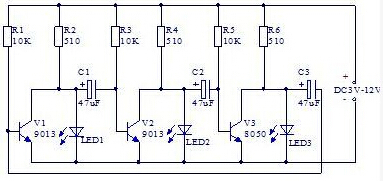
Working Principle:
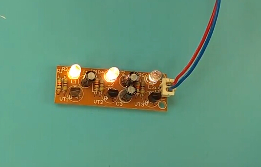
▲This circuit is a circular drive circuit composed of three transistors.
When the power is switched on, the three transistors will compete for the lead, but due to the differences in the components, only one transistor will lead the way. Here, let's assume that V1's most precursors, V1 collector voltage drop, makes the left end of capacitor C2 go down, approaching 0V.
▲Because at the ends of the capacitor voltage mutation, and so is the base of the V2 pulled to approximate 0 v, deadlines, collector for high voltage V2, V2 so pick up on it to LED2. At this point the V2 by high voltage capacitor C3 V3 base voltage increases, the V3 will rapidly conduction. So during this time, V1 and V3 collector are low voltage, only LED2 lit up, LED1, LED3 extinguished.
▲However, as the power supply is charged to C2 with the resistance of R3, the base voltage of V2 gradually increases, and when more than 0.7 V, V2 is transformed from the cut-off state to the leading state, the collector voltage drops, and the LED2 dies out.
▲At the same time, the voltage of the collector of V2 decreases with the capacitance of C3, which makes the base voltage of V3 lower, and V3 is turned into the cut-off, and the collector voltage of V3 is increased, and LED3 is illuminated.
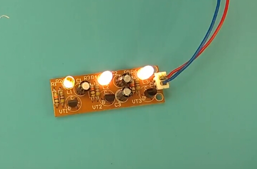
▲Next, the circuit loops through the process described above, and the three LED will be lit up in turn, and the cycle will continue to glow and achieve the effect of flow. Changing the capacity of capacitors C1, C2, and C3 can change the cycle speed, the smaller the capacity, the faster the cycle.
Circuit Diagram:
Component List:
| NO. | Component Name | PCB Marker | Parameter | QTY |
| 1 | Electrolytic Capacitor | C1-C3 | 47uf 25V | 3 |
| 2 | S9013 | V1-V3 | TO-92 | 3 |
| 3 | LED | LED1-LED3 | 5mm | 3 |
| 4 | Metal Film Resistor | R1,R3,R5 | 10K | 3 |
| 5 | Metal Film Resistor | R2,R4,R6 | 510ohm | 3 |
| 6 | Male Pin | DC | 2.54mm 2P | 1 |
| 7 | PCB | 18*53mm | 1 |
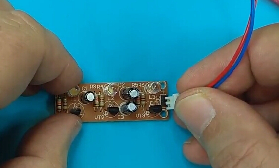
Tested by ICStation's Outstanding Partner bzoli5706:
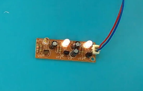
Learn More Details in the Video:


