- prev
- next
DIY Kit FM Stereo Radio Module with Headset Adjustable 76-108MHz Wireless Receiver DC 3V
$4.89$6.9930%
| Quantity | 5+ | 10+ | 30+ | 50+ |
| Price | $4.50 | $4.20 | $3.80 | $3.30 |
00d : 00h : 00m : 00s
Item ID: GY18043
Product Details
Reviewed by ICStation's Outstanding Partner Stefano91ste
Reviewed by ICStation's Outstanding Partner todderbert
1.Introduction:
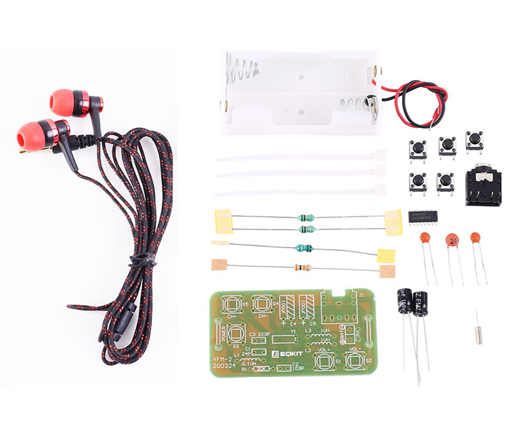
The YFM-2 type radio circuit is very simple. The total number of components does not exceed 19. Although the number of components is not much, it still includes two types of components: SMD and DIP which are suitable for novices and friends who want to practice soldering of SMD components.
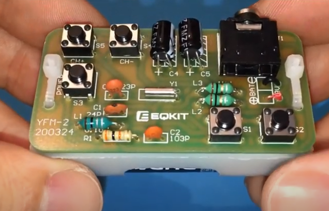
(Finished products after installation)
2.Feature:
1>.Built-in digital automatic gain control (AGC) circuit
2>.Support the global frequency band 76-108Mhz
3>.Simple and easy to operate
4>.Support radio memory function
3.Parameter:
1>.Item name: FM Stereo Radio DIY Kit (battery not included)
2>.Item Mode:YFM-2
3>.Work Voltage:DC 3V
4>.Work Current:19mA
5>.Work Frequency:76-108Mhz
6>.Output impedance:32ohm
7>.Work Temperature:-40℃~85℃
8>.Work Humidity:0%~95%RH
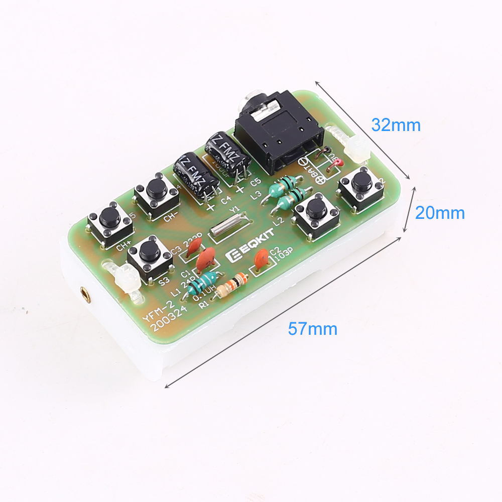
9>.Size(Installed):57*32*20mm
4.Installation Tips:
1>.User needs to prepare the soldering tool at first.
2>.Please be patient until the installation is complete.
3>.The soldering iron can't touch the components for a long time(1.0 second), otherwise it will damage the components.
4>.Pay attention to the positive and negative of the components.
5>.Strictly prohibit short circuit.
6>.Install complex components preferentially.
7>.Make sure all components are in right direction and right place.
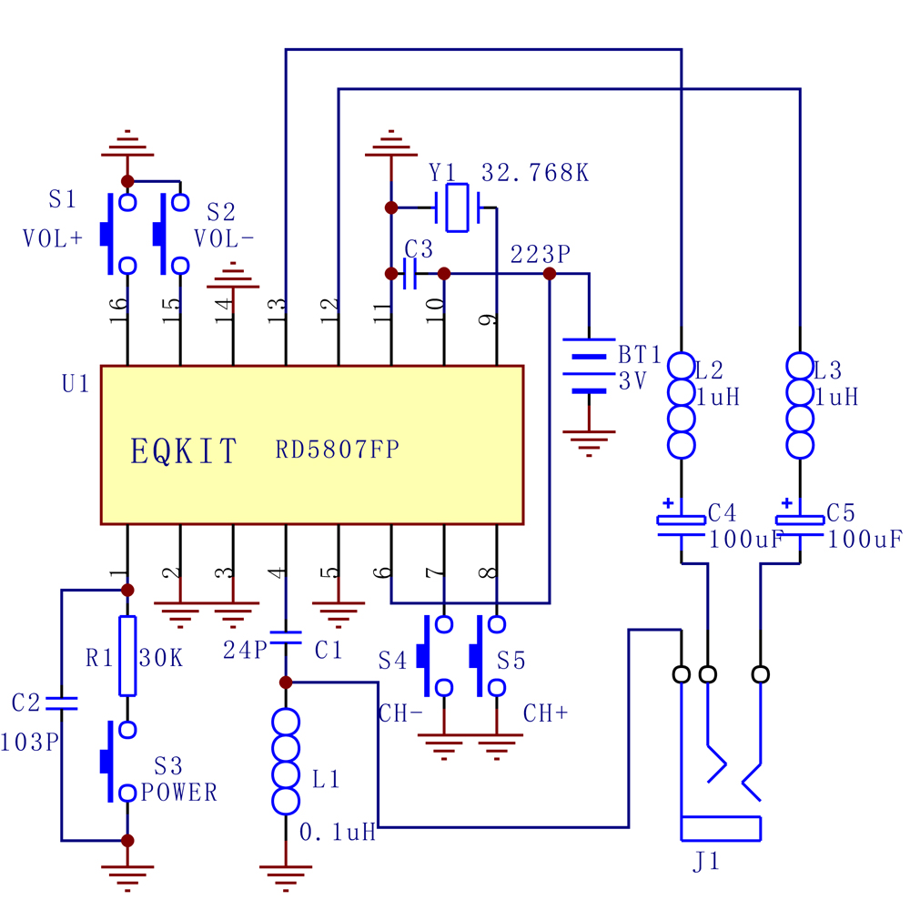
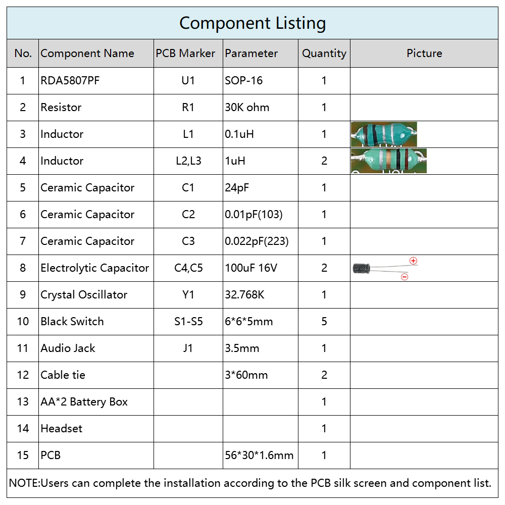
5. Circuit Diagram & Components List:
6.Installation Steps(Please be patient):
Step 1: Install 1pcs SOP-16 RDA5807PF at U1.There is a dot on one corner of the IC and there is a rectangle pad on PCB where the Pin1 of IC can place on.These two marks are corresponding to each other and are used to specify the installation direction of the IC.
Step 2: Install 1pcs 32.768KHz Crystal Oscillator at Y1.
Step 3: Install 1pcs 30K ohm Resistor at R1.
Step 4: Install 1pcs 0.1uH Inductor at L1.
Step 5: Install 2pcs 1uH Inductor at L2,L3.
Step 6: Install 1pcs 24pF Ceramic Capacitor at C1.
Step 7: Install 1pcs 0.01pF(103) Ceramic Capacitor at C2.
Step 8: Install 1pcs 0.022pF(223) Ceramic Capacitor at C3.
Step 9: Install 5pcs 6*6*5mm Switch at S1-S5.
Step 10: Install 1pcs 100uF 16V Electrolytic Capacitor at C4,C5. Please pay attention to the positive and negative poles. The shorter pin is the negative pole.
Step 11: Install 1pcs 3.5mm Audio Jack at J1.
Step 12: Connect battery box.Pay attention to positive and negative.
Step 13: Use a cable tie to fasten the battery box.
Step 14: Connect to power supply and make it works.