- prev
- next
DIY Kit 3D Xmas Tree RGB Flash LED Circuit Colorful Christmas Trees LED Soldering Practice Kit DC 4.5V~5.5V
$13.29$18.9930%
| Quantity | 3+ | 5+ | 10+ |
| Price | $13.00 | $12.70 | $12.20 |
00d : 00h : 00m : 00s
Item ID: GY18150
Product Details
1.Introduction:
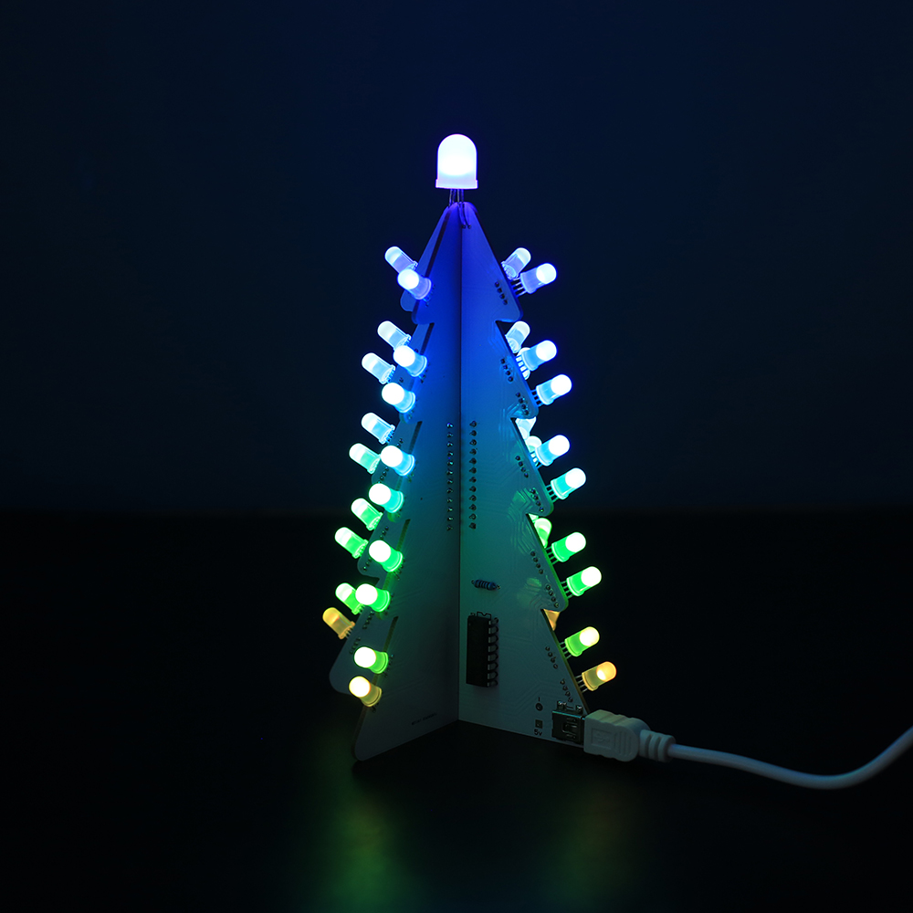
It is a flash Christmas tree kit consists of three circuit board, allows 36 LED flash alternately, showing a Christmas tree in the space of three-dimensional profile (the night environment has better viewing).
2.Feature:
1>.36pcs highlight RGB full color LED
2>.14 kinds of display effects
3>.Photo sensor automatically adjusts LED brightness
4>.Toggle Switch control flashing mode
5>.5mm/10mm big LED
6>.Perfect simple circuit
3.Parameter:
1>.Work Voltage:DC 4.5V~5.5V
2>.Work Current:500mA
3>.Power Type:Mini USB
4>.Work Module:Switch Control
5>.Color:RGB LED
6>.Work Temperature:-40℃~85℃
7>.Work Humidity:0%~95%RH
8>.Size(Installed):88*88*160mm
4.Display Mode:
1>.Christmas rainbow gradient mode
2>.Meteor impact mode
3>.Simulate Starlit mode
4>.All slow color changing
5>.Up and down meteor mode
6>.Aurora color gradient mode
7>.Middle color changing mode
8>.Similar color slow changing mode
9>.Multi-color small meteor crossing mode
10>.Similar color diffusion in the middle mode
11>.Random color lightning mode
12>.Rainbow color flashing mode
13>.Meteor across color gradient mode
14>.Meteor back and forth across mode
5.Application:
1>.Training soldering skills
2>.Electronic Projects Ideas for School Students
3>.Crafts collection
4>.Home decoration
5>.Holiday gifts
6.Installation Tips:
1>.User needs to prepare the welding tool at first.
2>.Please be patient until the installation is complete.
3>.The package is DIY kit.It need finish install by user.
4>.The soldering iron can't touch the components for a long time(1.0 second), otherwise it will damage the components.
5>.Pay attention to the positive and negative of the components.
6>.Strictly prohibit short circuit.
7>.User must install the LED according to the specified rules.Otherwise some LED will not light.
8>.Install complex components preferentially.
9>.Make sure all components are in right direction and right place.
10>.Check that all of the LED can be illuminated.
11>.It is strongly recommended to read the installation manual before starting installation!!!
12>.The default code inside the chip, the function is more abundant,So please do not update the code inside arbitrarily!!!
7.Installation Steps(Please be patient install!!!):
Step 1: Identify the LED pins. The rectangular pad connects to the longest LED pin.The pins of other LED are inserted into the corresponding pads in sequence.
Step 2: Place LED on pad and then bend LED and keep about 2mm distance between PCB edge and LED body.And then fixed LED pin.
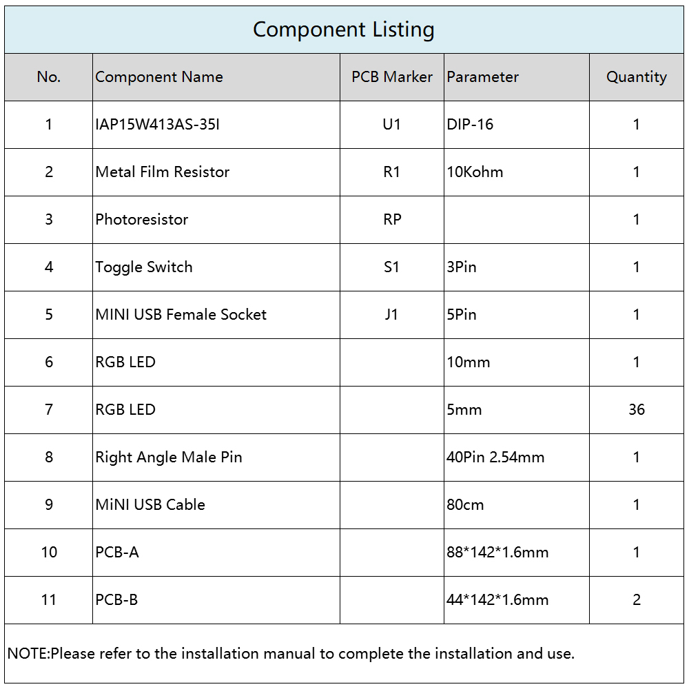
Step 3: Install 1pcs 10Kohm Metal film resistor at R1 and 1pcs Photoresistor at RP on the bigger PCB.
Step 4: Install 1pcs MINI USB Female Socket at J1 on the bigger PCB.
Step 5: Install 1pcs DIP-16 IAP15W413AS-35I at U1 on the bigger PCB.There is a dot on one corner of the IC and there is a mark on PCB where the IC can place on.These two marks are corresponding to each other and are used to specify the installation direction of the IC.
Step 6: Install 1pcs Toggle Switch at S1 on the bigger PCB.
Step 7: Install 12Pin Male Pin at black area on 2pcs the smaller PCB.
Step 8: Fix 3pcs PCB.
Step 9: Install 1pcs 10mm RGB LED at the top.
Step 10: Connect to power supply and enjoy the effect.
.jpg)