Your Shopping Cart Is Empty!
If you already have an account, Sign in.
If you already have an account, Sign in.


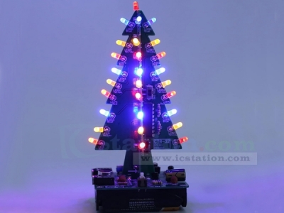
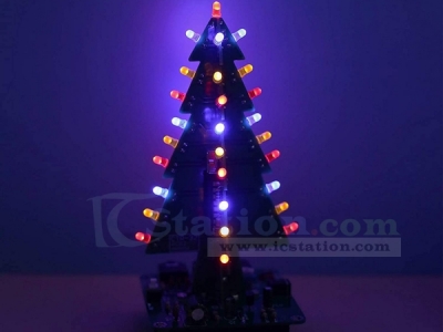
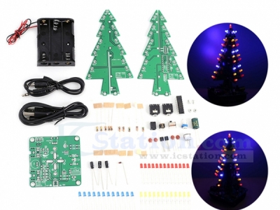
CRT-32 Audio LED Christmas Tree DIY Kit
1.Introduction:
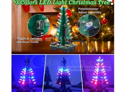
2.Feature:
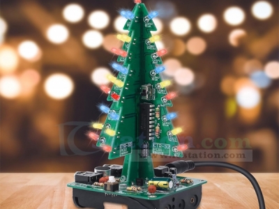
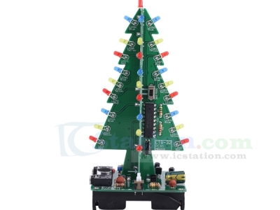
37pcs highlight LED.
Perfect simple circuit.
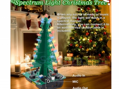
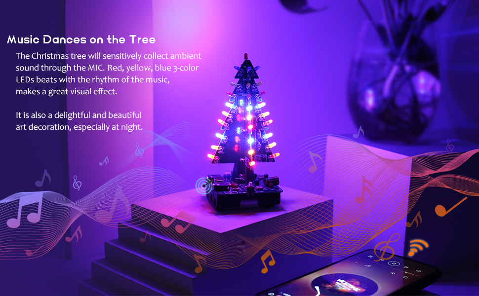
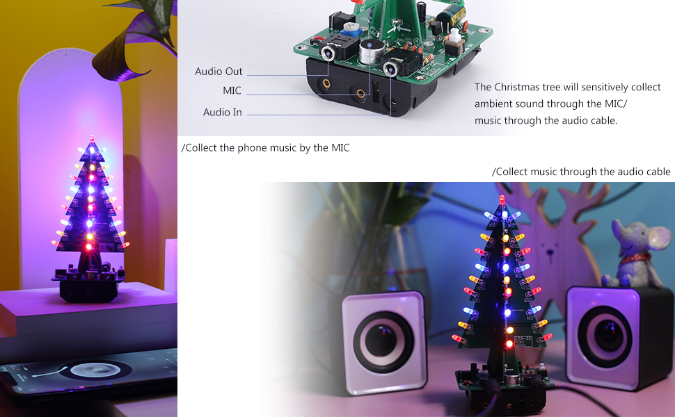
Sound Control audio display.
Support microphone and audio socket input.
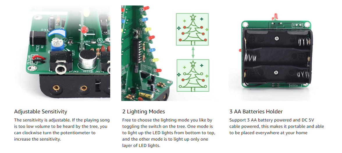
Adjustable sensitivity.
Two display modes.
3.Parameter:
1>.Product Name:CRT-32 Audio LED Christmas Tree DIY Kit
2>.Product Number:CRT-32
3>.Work Voltage:DC 4.0V~5.0V
4>.Work Current:60mA
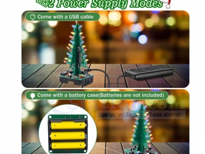
5>.Power Type:Battery Box and 3.5mm Power Socket
6>.Work Module:Switch Control
7>.Color:Red/Yellow/Blue LED
8>.Audio input:3.5mm audio socket and microphone
9>.Work Temperature:-40℃~85℃
10>.Work Humidity:5%~85%RH
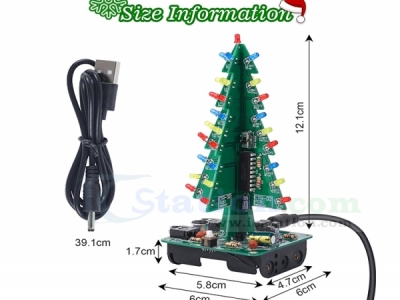
11>.Size(Installed):135*60*60mm
4.Installation Manual (Please be patient):
.png)
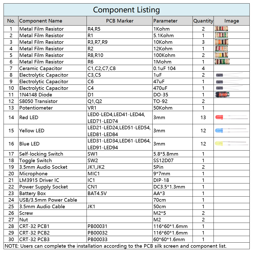
5. Component List:
This spectrum Christmas tree has an innovative design and a perfect combination of fun, learning, and art, which is suitable for both electronic enthusiasts and school students.
This is a parts kit and you need to solder them together to get a Christmas tree. Soldering this requires basic electronic knowledge.
| Quantity | 3+ | 5+ | 10+ |
| Price | $8.00 | $7.50 | $7.30 |
ICStation doesn't accept any form of pay on delivery. Items used to be shipped after payment. Below are the payment methods we can accept at the moment:
1) Paypal Payment
PayPal is a secure and trusted payment processing service that allows you to shop online. PayPal can be used at icstation.com to purchase items by Credit Card (Visa, MasterCard, Discover, and American Express), Debit Card , or E-check (i.e. using your regular Bank Account).

We are PayPal Verified 
2) Bank Transfer / Wire Transfer / T/T
Bank Transfer / Wire Transfer / T/T payment methods are accepted for orders which the total price is up to US$300. The bank will charge about US$50 for the transfer fee if we do the payment in these ways. Feel free to contact us for bank payment details if you need pay via bank.
For other payment method, please contact us at orders@icstation-team.com for more details.