1.Description:
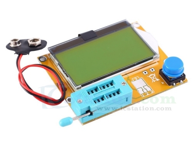
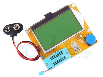
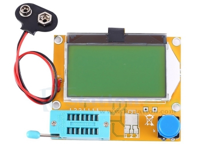
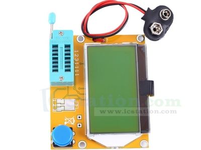
It is a LCR-T4 transistor tester.It uses an ATmega328 microcontroller.
The liquid crystal is a 12864 liquid crystal display with a backlight, and the backlight color is generally yellow-green.Powered by 9v stacked batteries.
If you supply power for a long time, you can use an 8.4v battery pack with 2 lithium batteries to supply power.
2.Feature:
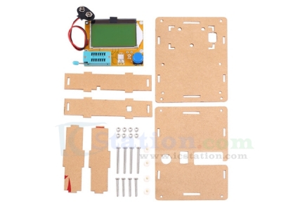
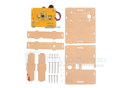
1.Comes with acrylic case
2.LCD12864 large screen display
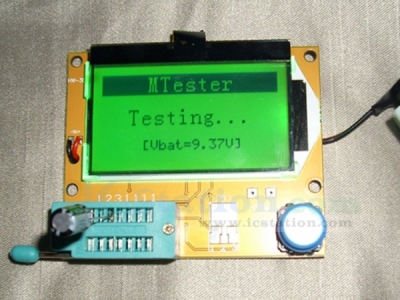
3.Support boot voltage detection function
4.Automatic detection of NPN and PNP transistors,N-channel and P-channel MOSFETs,diodes (including dual diodes),thyristors,transistors,resistors and capacitors.
5.The pin of the component is automatically tested and displayed on the LCD.
6.Higher test speed,valid component test is 2 seconds.(Except for larger capacitors,the measurement of large capacitors also takes a long time,and the measurement time of 1 minute is normal)
7.Automatic shutdown function can avoid unnecessary waste,save battery energy and improve battery life.
8.One-button operation automatically turns off the power.
9.The ATmega328 uses sleep mode to reduce power consumption when not in measurement.
3.Parameter:
1.Product Name:LCR-T4 Transistor Tester
2.Supply Voltage: DC9V
3.Resistance Measurement Resolution:0.1 ohm
4.Maximum Measurement Value:50M ohm
5.Work Temperature:-25℃~85℃
6.Work Humidity:5%~95%RH
7.Size:86*60.5*18.5mm
8.Resistor: 0.1ω-50Mω
9.Capacitor: 25pF-100000uF
10.Inductance: 0.01mH - 20H
11.Standby current: 0.02uA
12.Operating current: 25mA
4.Note:
1.The shutdown current is only 20nA,which supports battery operation.
2.Measure the current amplification factor of the bipolar transistor and the threshold voltage of the emitter junction.
3.Darlington transistors can be identified by high threshold voltages and high current amplification factors.
4.It supports two resistance measurement and symbol display,up to four digits and unit display.The resistance symbol shown is at both ends of the connected tester probe number (1-3).So the potentiometer can also measure.If the potentiometer is adjusted to one end,the tester cannot distinguish between the middle and two ends of the pins.
5.It can measure the equivalent series resistance (ESR) capacitance value of capacitors with a value above 2UF.
6.It can show the sign of the correct direction for the two diodes and the forward voltage drop.
7.The LED is detected as a diode and the forward voltage drop is much higher than normal.The dual light emitting diode is detected as a dual diode.
8.Zener diodes can be detected if the reverse breakdown voltage is below 4.5V.This will appear as two diodes and can only be determined by voltage.The sign of the probe around the diode is the same,in which case you can identify the true anode of the diode by a threshold voltage near 700mV.
9.If more than 3 diode-type parts are detected,the number of established diodes displays another failure message.If a diode is connected to all three probes and at least one is a type diode.In this case,you should just connect the two probes and start the measurement again,one after the other.
10.Measure the reverse capacitance of a single diode.If you connect the base to the collector or emitter,bipolar transistors can also measure.
11.Capacitors with values below 25pf are usually not detected,but can be connected in parallel with a diode or at least 25pf capacitors.In this case,you must subtract the part of the shunt capacitance.
12.The test time is about two seconds,and only capacitance and inductance measurements take longer.
13.The software can set the number of measurements before the power is automatically turned off.
14.If the test current exceeds the sustain current,thyristors and triacs can be detected.But some semiconductor thyristors and triacs have higher trigger currents than the tester can provide.The available test current is only about 6mA.
5.Rotary Encoder Switch Control Button:
1.The rotary encoder switch can have 4 kinds of operations in total,short press,long press,left-hand and right-hand.
2.Short press once in the shutdown state to turn on the power and start the test.
3.After a test is completed,if no device is detected,you can long press the switch or the left and right rotary switches to enter the function menu.After entering the function menu,the left or right rotary switch can be selected up and down the menu item.To enter a certain function item,then Press the switch shortly.
6.Test Device:
1>.On the right side of the test stand is the test position of the chip component.There are numbers 1,2,and 3 respectively,each representing TP1,TP2,TP3.
2>.When testing a component with only 2 pins,the pins are in no particular order of testing.The 2 pins select 2 test points arbitrarily,and the 3 pin device pins are placed in three test points,regardless of order.
3>.After the test,the tester automatically recognizes the pin names and test points of the components and displays them on the screen.
4>.When testing components with only two pins,if two test points TP1 and TP3 are used,the test will automatically enter the continuous test mode after the test is completed,so that the components on TP1 and TP3 can be continuously and synchronously measured without pressing the switch.If you are using the "TP1 and TP2" or "TP2 and TP3" test,only test once.If you want to test again,press the switch once.
7.Calibration:
1>.The tester calibration is used to eliminate the errors of its own components and make the final test results more accurate.Calibration is divided into quick calibration and full-function calibration.
2>.Operation method of quick calibration:
1.1>.Short-circuit the three test points TP1,TP2,and TP3 with wires,and then press the test button while paying attention to the screen.The screen color will change to white text on a black background.After the prompt message "Selftest mode ..?" Appears,press the test button once to enter the quick calibration process.
1.2>.If after the prompt message "Selftest mode ..?" Appears,there is no key press within 2 seconds,a normal test process is performed,and finally the resistance value of the short test leads TP1,TP2,and TP3 is displayed.
1.3>.After entering the quick calibration process,some data will appear on the screen,regardless of him.Wait until the flashing character string "isolate Probes!" Appears on the screen,then remove the wires shorting TP1,TP2,TP3.Until the string "Test End" appears on the screen,the quick calibration is completed.
3>.Function calibration method:
1.1>.For the first calibration,the full-function calibration method is used.Full-function calibration needs to be entered from the function menu,and a 220nf capacitor is required.Full-featured calibration performs a more comprehensive calibration process and will take longer.
1.2>.After entering the function menu,rotate the test button to the menu item "Selftest",and then press the test button to enter the full-function calibration process.The flashing string "short Probes!" Will appear on the screen first.At this time,it is the same as the quick calibration.Short-circuit the three test points with a wire and wait for the calibration process to take place.When the flashing string "isolate Probes!" Appears on the screen,remove the wire shorted at the three test points and continue to wait for the calibration process to proceed.When the character string "1-||-3> 100nf" is output,install the prepared 220nf capacitor on the test points TP1 and TP3.
1.3>.Wait until the screen prompts "Test End" and the full-function calibration process is complete.
8.Package:
1pcs LCR-T4 Transistor Tester
8pcs Screws
8pcs Nuts
Arcylic Case