Your Shopping Cart Is Empty!
If you already have an account, Sign in.
If you already have an account, Sign in.


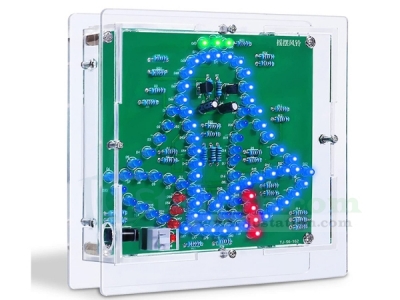
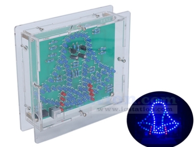
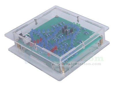
Electronic LED Wind Chime DIY Kit
1.Introduction:
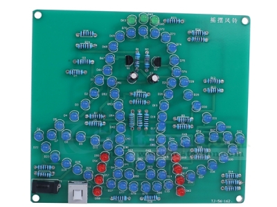
It is a Electronic LED Wind Chime DIY Kit. It simulates the swing of the wind chime through the flashing of the LED. It is a very interesting DIY electronic product which enables users to understand the circuit more clearly and learn soldering skills.
2.Feature:
1>.LED flashes automatically
2>.Controllable self-locking switch
3>.Acrylic shell
4>.Simple circuit
5>.DIY soldering project
3.Parameter:
1>.Product Name:Electronic LED Wind Chime DIY Kit
2>.Work Voltage:DC 4.5V-5V
3>.Work Temperature:-20℃~85℃
4>.Work Humidity:5%~85%RH
5>.Size(Installed):112*107*30mm
4.Use Steps:
1>.Connect work voltage DC4.5V-5V from 3.5mm socket by USB wire.
2>.Press switch to turn ON LED flashes.
3>.Press again to turn OFF.
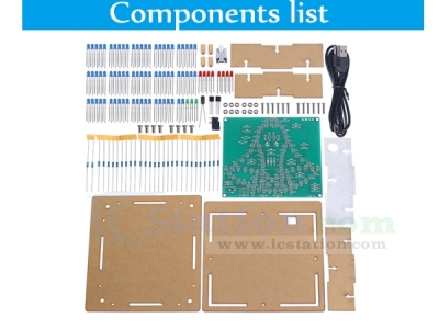
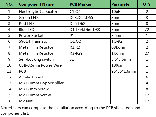
5.Components List:
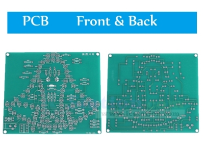
6.Installation Steps (Please download the PDF User Manual here):
.png)


| Quantity | 5+ | 10+ | 30+ |
| Price | $10.99 | $10.70 | $10.30 |
ICStation doesn't accept any form of pay on delivery. Items used to be shipped after payment. Below are the payment methods we can accept at the moment:
1) Paypal Payment
PayPal is a secure and trusted payment processing service that allows you to shop online. PayPal can be used at icstation.com to purchase items by Credit Card (Visa, MasterCard, Discover, and American Express), Debit Card , or E-check (i.e. using your regular Bank Account).

We are PayPal Verified 
2) Bank Transfer / Wire Transfer / T/T
Bank Transfer / Wire Transfer / T/T payment methods are accepted for orders which the total price is up to US$300. The bank will charge about US$50 for the transfer fee if we do the payment in these ways. Feel free to contact us for bank payment details if you need pay via bank.
For other payment method, please contact us at orders@icstation-team.com for more details.