Your Shopping Cart Is Empty!
If you already have an account, Sign in.
If you already have an account, Sign in.


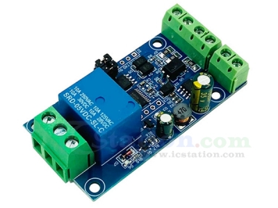
1.Description:
It is a single relay module. The single channel relay module is equipped with a mature and stable 8-bit MCU and RS485 level communication chip. Using standard MODBUSRTU format RS485 communication protocol, it can realize 1 optical coupler input signal detection and 1 relay output,which can be used for digital quantity detection or power control occasions.
2.Feature:
1).It uses mature and stable 8bit MCU and MAX485 level conversion chip.
2).It supports the standard Modbus RTU protocol.
3).It supports RS485/TTL UART interface.
4).It has a relay switch indicator,you can see the working status of the product.
5).It supports the power-down save function.
6).Onboard 1 way 5V,10A/250V AC 10A/30V DC relay,which can be activated continuously for 100,000 times,has diode effusion protection,and has a short response time.
7).It has input anti-reverse protection.
3.Parameter:
1).Product Name:Single Relay Module
2).Supply Voltage:DC 7V-24V
3).Communication Protocol:support standard Modbus RTU protocol
4).Communication Interface:support RS485/TTL UART interface
5).Communication Baud Rate:4800/9600/19200 (default 9600bps)
6).Optocoupler Input Signal Range:DC3.3V-30V(this input cannot be used for relay control)
7).Device Address:range 1-255 (default 255).
8).Work Temperature:-25℃~85℃
9).Work Humidity:5%~95%RH
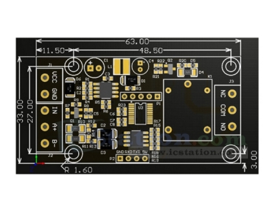
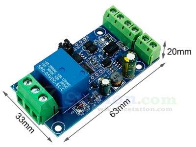
10).Size:63*33*20mm
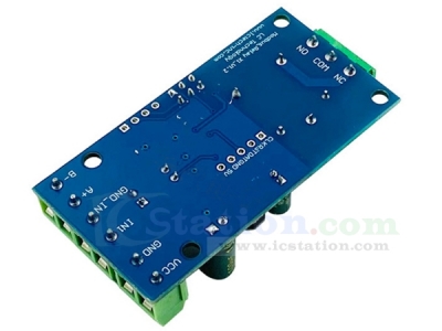
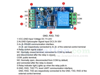
4.Interface Definition:
1).VCC,GND:Input DC 7V-24V
2).IN,GND:DC 3.3-30V optocoupler signal input
3).A+,B-:RS485 communication interface,A+,B are respectively connected to A+,B- of the external control terminal
4).Relay switch signal output:
1.1).NC:Normally closed,the relay is short-connected with COM before it is closed,and it is suspended after it is closed;
1.2).COM:public end;
1.3).NO:Normally open end,the relay is suspended before the pull-in,and short-circuited with COM after the pull-in.
5).Relay indicator:it lights up when the relay is closed
6).GND,RXD,TXD:TTL level UART communication interface,GND,RXD,TXD are respectively connected to GND,TXD,RXD of the external control terminal
5.Introduction to Modbus RTU Command:
1).Modbus devices perform related operations by receiving Modbus RTU commands from an external control terminal (such as:host computer/MCU).A frame of command generally consists of device address,function code,register address,register data,and check code.The frame length related to function codes.Generally,the first byte of each frame of data is the device address,and the settable range is 1-255,the default is 255 (ie 0xFF),and the last 2 bytes are the CRC check code.
2).Assuming that the device address is 255,the commonly used:
1.1).Turn on the No.1 relay (manual mode)
Send:FF 05 00 00 FF 00 99 E4
Return as is:FF 05 00 00 FF 00 99 E4
Remarks:(1) The 3-4 bytes of the sending frame represent the relay address,the addresses of relay 1-relay 8 are 0x0000,0x0001,0x0002,0x0003,0x0004,0x0005,0x0006,0x0007 respectively
(2) The 5-6 bytes of the sending frame represent data,0xFF00 represents opening the relay,and 0x0000 represents closing the relay.
1.2).Turn off No.1 relay (manual mode)
Send:FF 05 00 00 00 00 D8 14
Return as is:FF 05 00 00 00 00 D8 14
1.3).Turn on all relays
Send:FF OF 00 00 00 08 01 FF 30 1D
Return:FF 0F 00 00 00 08 41 D3
1.4).Turn off all relays
Send:FF 0F 00 00 00 08 01 00 70 5D
Return:FF OF 00 00 00 08 41 D3
1.5).Set the device address to 1
Send:00 10 00 00 00 01 02 00 01 6A 00
Return as is:00 10 00 00 00 01 02 00 01 6A 00
Note:The ninth byte 0x01 of the sending frame is the device address written
1.6).Set the device address to 255
Send:00 10 00 00 00 01 02 00 FF EB 80
Return as is:00 10 00 00 00 01 02 00 FF EB 80
Note:The ninth byte 0xFF of the sending frame is the device address written
1.7).Read the device address
Send:00 03 00 00 00 01 85 DB
Return:00 03 02 00 FF C5 C4
Note:The 5th byte 0xFF of the return frame is the read device address
1.8).Read the relay status
Send:FF 01 00 00 00 08 28 12
Return:FF 01 01 01 A1 A0
Remark:Bit0--Bit7 of the 4th byte 0x01 of the return frame respectively represent relay 1--relay 8,0 is closed,1 is open.
1.9).Read the optocoupler input status
Send:FF 02 00 00 00 08 6C 12
Return:FF 02 01 01 51 AO
Note:IN1--IN8 of the 4th byte 0x01 of the return frame respectively represent the input signal of optocoupler 1-- optocoupler 8,0 represents low level,1 represents high level
1.10).Set the baud rate to 4800
Send:FF 10 03 E9 00 01 02 00 02 4A 0C
Return:FF 10 03 E9 00 01 C5 A7
Note:The 9th byte of the sending frame is the baud rate setting value,0x02,0x03,x04 represent 4800,9600,19200 respectively
1.11).Set the baud rate to 9600
Send:FF 10 03 E9 00 01 02 00 03 8B CC
Return:FF 10 03 E9 00 01 C5 A7
1.12).Set the baud rate to 19200
Send:FF 10 03 E9 00 01 02 00 04 CA 0E
Return:FF 10 03 E9 00 01 C5 A7
1.13).Read baud rate
Send:FF 03 03 E8 00 01 11 A4
Return:FF 03 02 00 04 90 53
Note:The 5th byte of the returned frame represents the read baud rate,0x02,0x03,x04 represent 4800,9600,19200 respectively.
1.14).Turn on the No.1 relay (flash closing mode 2S)
Send:FF 10 00 03 00 02 04 00 04 00 14 C5 9F
Return:FF 10 00 03 00 02 A4 16
Remarks:(1) The 3-4 bytes of the sending frame represent the relay address,the addresses of relay 1-relay 8 are 0x0003,0x0008,0x000D,0x0012,0x0017,0x001C,0x0021,0x0026 respectively
(2) The 10th-11th bytes of the sending frame represent the delay setting value,the delay base is 0.1s,so the delay time is 0x0014*0.1=20*0.1S=2S,the relay will automatically close after 2S is turned on.
1.15).Turn off No.1 relay (flash mode 3S)
Send:FF 10 00 03 00 02 04 00 02 00 1E A5 99
Return:FF 10 00 03 00 02 A4 16
Remarks:(1) The 3-4 bytes of the sending frame represent the relay address,the addresses of relay 1--relay 8 are 0x0003,0x0008,0x000D,0x0012,0x0017,0x001C,0x0021 ,0x0026 respectively
(2) The 10th-11th bytes of the sending frame represent the delay setting value,the delay base is 0.1S,so the delay time is 0x001E*0.1=30*0.1S=3S,the relay will automatically turn on after 3S is closed
6.Simple Instructions for Use:
1).The Modbus relay module can receive Modbus RTU commands from the host computer/MCU via the RS485/TTL UART interface to perform related operations.The following is an example of using the host computer software to open relay 1 (manual mode) through the RS485 interface.Assuming that the device address is 255 and the baud rate is 9600,the steps are as follows:
2).VCC,GND are respectively connected to the positive and negative poles of the power supply.
3).A+ and B- are A+ and B- at the output end of the USB to RS485 module respectively.
4).Open the host computer software "ModbusRTU Configuration Tool",select the correct port number,select 9600 for the baud rate,set the address to 255,and click "Open Serial Port".
5).Then click "JD1 ON" to turn on relay 1,and the indicator light of relay 1 will be on at the same time.
7.How to Generate Check Code:
1).When the Modbus RTU command is sent through the ready-made host computer software (such as:ModbusRTU configuration tool),the CRC check code is automatically generated.If you want to use serial debugging software (such as SSCOM) to test the Modbus relay module,you need to manually generate CRC The check code is placed at the end of the sending frame,such as opening the first relay (manual mode):
2).The sending frame composition of open/close relay (manual mode) is:Device address (1Byte) + function code (1Byte) + register address (2Byte) + register data (2Byte) + CRC check code (2Byte)
3).Assuming the device address is 0xFF,the first 6 bytes of the transmitted frame are:FF 05 00 00 FF 00
4).Use the CRC check tool to find the check code for these 6 bytes.
5).After exchanging the high and low byte positions of the check calculation result E499,the CRC check code 99E4 is obtained,and the complete sending frame:FF 05 00 00 FF 00 99 E4.
6).Send the frame to the Modbus relay module through the serial port debugging software SSCOM V5.13.1 to open the first relay (manual mode).
8.Package:
1pcs Single Relay Module
ICStation doesn't accept any form of pay on delivery. Items used to be shipped after payment. Below are the payment methods we can accept at the moment:
1) Paypal Payment
PayPal is a secure and trusted payment processing service that allows you to shop online. PayPal can be used at icstation.com to purchase items by Credit Card (Visa, MasterCard, Discover, and American Express), Debit Card , or E-check (i.e. using your regular Bank Account).

We are PayPal Verified 
2) Bank Transfer / Wire Transfer / T/T
Bank Transfer / Wire Transfer / T/T payment methods are accepted for orders which the total price is up to US$300. The bank will charge about US$50 for the transfer fee if we do the payment in these ways. Feel free to contact us for bank payment details if you need pay via bank.
For other payment method, please contact us at orders@icstation-team.com for more details.