Home > Power Module > Step Down Module > DC-DC 5A Step Down Power Supply Module LCD Display Constant Voltage Constant Current Adjustable Buck Converter CVCC Adapter
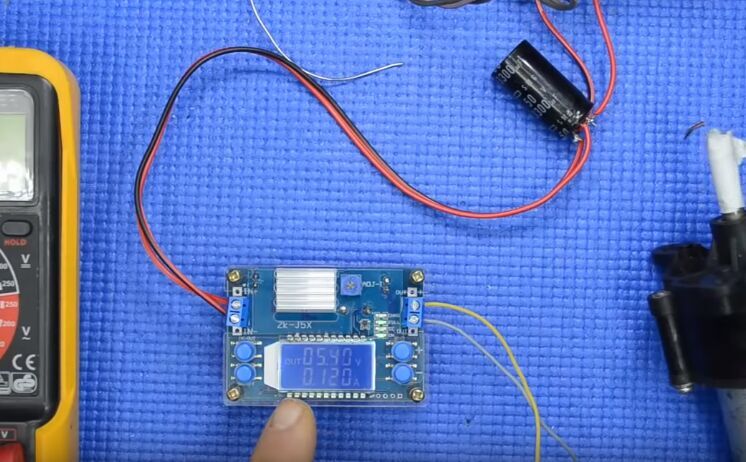
13>.Multiple parameters are displayed simultaneous;
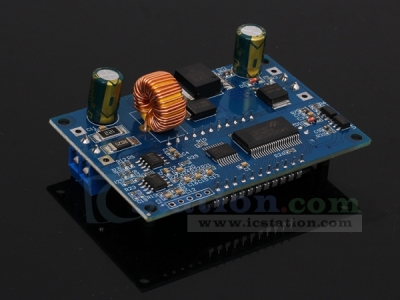
14>.High current, low heat;
3.Parameters:
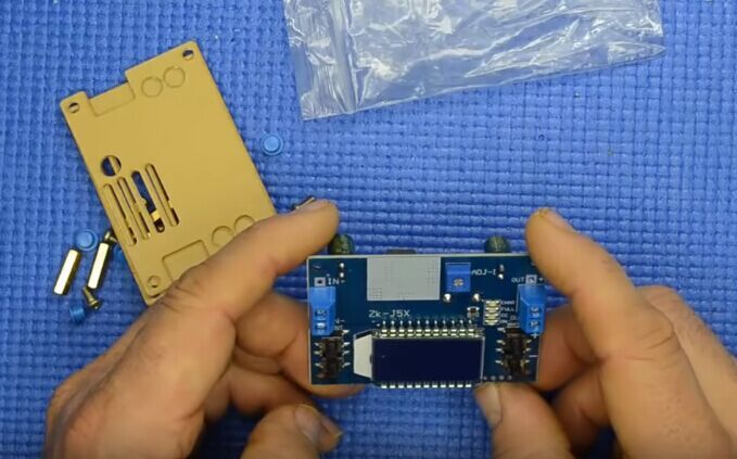
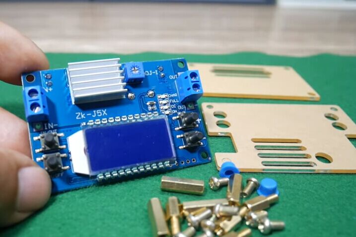
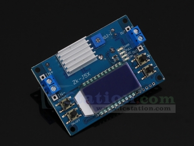
1>.Product Name:ZK-J5X 5A Step Down Power Supply Module
2>.Product Number:ZK-J5X
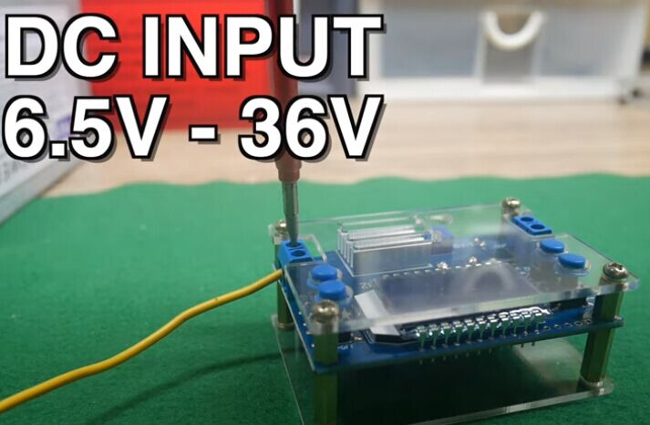
3>.Working Voltage:DC 6.5V-36V
4>.Output Voltage:DC 1.2V-32V
5>.Output Current:5A (4.5A need heat sink;3.5A is stable for long time)
6>.Output Power:75W(75W need heat sink;50W is for 3.5A)
7>.Voltage Display Range:1.2~32V
8>.Voltage Display Precision:+/-0.1V
9>.Voltage Display Resolution:0.05
10>.Current Display Range:0~5A
11>.Current Display Precision:+/-0.05A
12>.Voltage Display Resolution:0.005A
13>.Conversion efficiency:About 94%
14>.Working current:30mA
15>.Soft Starter:Yes(Failure at high power load)
16>.Anti-reverse Protection:Yes
17>.Anti-backflow Protection:No (It is recommended to connect a diode in series at the ‘OUT+’)
18>.Working Temperature range:-20℃~85℃
19>.Working Humidity range:0%-95%RH
20>.Size without shell:68*47*26mm
21>.Size with shell:70.5*48.4*30mm
22>.Heat Sink Size:20*14*6mm
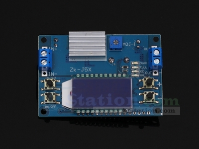
4.Button/Potentiometer/LED introduction:
1>.Long press means need keep press for more than 3second.
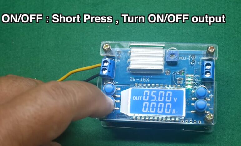
2>.ON/OFF:Short Press to select whether output voltage.Long press is used to restore default settings for next re-power.
3>.IN/OUT:Short Press to switch display input voltage or output voltage.Long press is used to switch display output current or output power.
4>.’+’ Button:It is used to regulate output voltage.Increase output voltage.Each time the button is pressed for short press,the output voltage is increased by 0.05V.Long press can continuously increase.Increase 0.1V, 1V in continuous if keep long press again.
5>.’ - ’ Button:It is used to regulate output voltage.Decrease output voltage.Each time the button is pressed for short press,the output voltage is decreased by 0.05V.Long press can continuously decrease.Decrease 0.1V, 1V in continuous if keep long press again.
6>.ADJ-I Potentiometer:Adjust output current.Increase the output current when rotating clockwise.Module enters constant current output state if load current reach the Set Current Value.Constant current Red LED indicator CC will turn ON.
7>.ON LED:Green LED.Output indicator.It will turn ON when there is a output at output terminal.Otherwise it is OFF.
8>.CC LED:Red LED.Constant current output indicator.It enters the constant current state when the load current reaches the set current and CC constant current indicator turns ON.
9>.FULL LED:Green LED.Charged fully indicator.When battery is charged fully.It will turn ON.It will turn ON if output current is less than 0.2A when the Set Current is 2A.
10>.CHAR LED:Charging indicator.It will turn ON when charging.
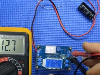
5.Using Steps:
1>.As a ordinary step down power module:
1.1>.Connect right input voltage at input terminal;
1.2>.Adjust ’+’ and ’ - ’ constant voltage buttons to set output voltage according to require.
1.3>.Rotate ADJ-I potentiometer counterclockwise more than 10 turns at first.
1.4>.Test Output short circuit current by multimeter at 10A or 20A(Connect two Test Probes to output terminal on module)
1.5>.Rotate ADJ-I constant current potentiometer clockwise to set output current according to require overcurrent protection value.
1.6>.Test and using(E.g:Module’s maximum output current is 2A if display 2A on multimeter.Then the maximum current can only be 2A when use this module.Red LED indicator will turn on if output reach to 2A.Otherwise LED is OFF.)
1.7>.The output voltage will decrease due to the current sampling resistor at the output. The higher the current, the more the voltage is reduced.
2>.As a charger:
2.1>.Tops:Power module can not be used as charger module if it does not support constant current function.The voltage difference between the battery with insufficient voltage and the charger is very large.That causes excessive charging current even damage the battery.So it needs keep charging in constant current mode to reaching a certain level.Then automatically switch back to constant voltage charging.
2.2>.Make sure floating charge voltage and charge current for battery.If the lithium battery’s parameter is 3.7V/2200mAh, then the float charge voltage is 4.2V, and the maximum charging current is 1C, which is 2200mA.
2.3>.Connect right input voltage at input terminal.(Note:Please don’t connect load during set parameter).
2.4>.Test output voltage by multimeter and adjust ’+’ and ’ - ’ constant voltage buttons to make sure output voltage reach to require floating charge voltage.(If charge a 3.7V lithium battery, adjust the output voltage to 4.2V)
2.5>.Rotate ADJ-I potentiometer counterclockwise more than 10 turns at first.
2.6>.Test Output short circuit current by multimeter at 10A or 20A(Connect two Test Probes to output terminal on module)
2.7>.Rotate ADJ-I constant current potentiometer clockwise to set output current according to require charge current value.
2.8>.Connect battery at output terminal and start to charging.
3>.As a high power LED constant current driver:
3.1>.Make sure LED’s working current and maximum working voltage.
3.2>.Connect right input voltage at input terminal.(Note:Please don’t connect load during set parameter).
3.3>.Test output voltage by multimeter at output terminal and adjust ’+’ and ’ - ’ buttons to set output voltage to LED’s maximum working voltage.
3.4>.Rotate ADJ-I potentiometer counterclockwise more than 10 turns.
3.5>.Test Output short circuit current by multimeter at 10A or 20A(Connect two Test Probes to output terminal on module)
3.6>.Rotate ADJ-I constant current potentiometer clockwise to set output current according to require LED working current.
3.7>.Connect LED and test.
6.Note:
1>.Default output voltage is about 5V.
2>.It is a step down power supply module,So the output voltage must be lower than input voltage.Otherwise it will not working normally.
3>.Please press button ’ - ’ repeatedly if there is no output voltage.
4>.It is a DC power module,So it can not connect to AC power.
5>.Please don’t short output.
6>.Input voltage must be 0.5V higher than output voltage.
7>.Please connect input before connect battery when use as charge and make sure output voltage is higher than battery voltage.It is recommended to serial a anti-backflow diode at input positive terminal.
8>.’IN-’ and ‘OUT-’ can not be connect together,otherwise module can not support constant current output.
9>.Please make sure input power is more than load power.
10>.Please step down output power if module is hot.
11>.The module's output voltage and current accuracy are 0.1V and 0.05A.
12>.Please read use manual and description before use.
7.Application:
1>.Ordinary power supply;
2>.Battery charger;
3>.LED drive power;
4>.Instrument voltage display;
5>.Test meter;
6>.Circuit test;
7>.Power conversion.
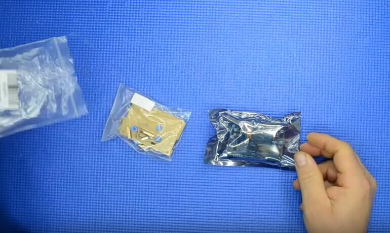
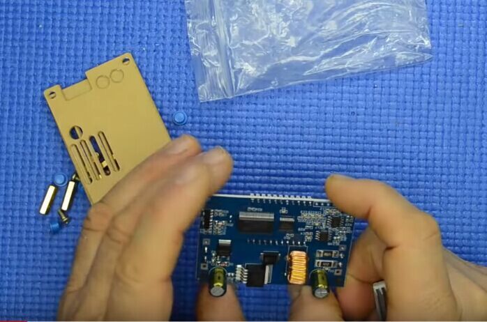
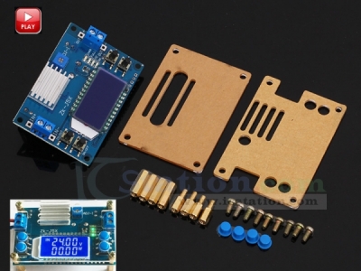
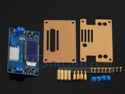
8.Package:
1pcs ZK-J5X 5A Step Down Power Supply Module;
1pcs 20*14*6mm Heat Sink;
2pcs Acrylic shell;
4pcs Blue button cap;
4pcs M3*15mm Copper column;
4pcs M3*8+6mm Copper column;
8pcs M3*5mm Screw.
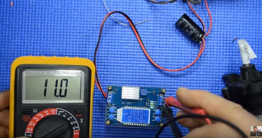
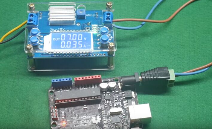
1. Tested by ICStation's Outstanding Partner ELECTROJUANYU:
Learn More Details in the Video: (The language in the video isSpanish)
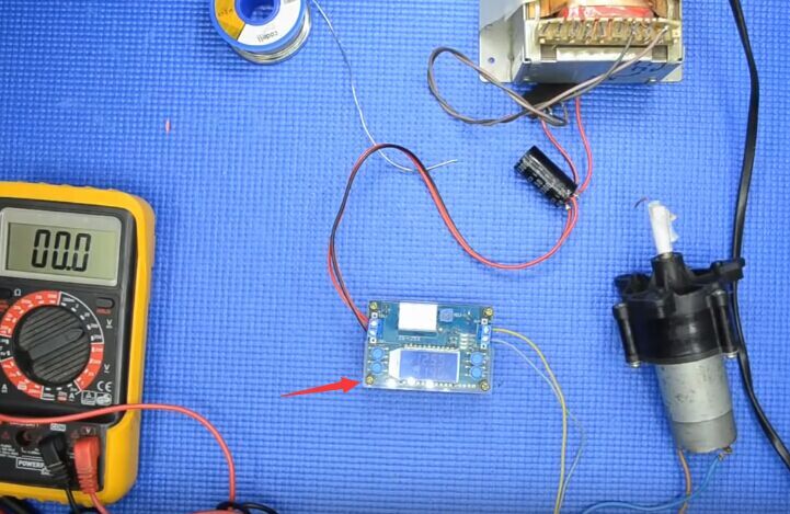
2. Tested by ICStation's Outstanding Partner Maker Tutor:
Learn More Details in the Video: (The language in the video isEnglish)
ICStation doesn't accept any form of pay on delivery. Items used to be shipped after payment. Below are the payment methods we can accept at the moment:
1) Paypal Payment
PayPal is a secure and trusted payment processing service that allows you to shop online. PayPal can be used at icstation.com to purchase items by Credit Card (Visa, MasterCard, Discover, and American Express), Debit Card , or E-check (i.e. using your regular Bank Account).
We are PayPal Verified
2) Bank Transfer / Wire Transfer / T/T
Bank Transfer / Wire Transfer / T/T payment methods are accepted for orders which the total price is up to US$300. The bank will charge about US$50 for the transfer fee if we do the payment in these ways. Feel free to contact us for bank payment details if you need pay via bank.
For other payment method, please contact us at orders@icstation-team.com for more details.