Your Shopping Cart Is Empty!
If you already have an account, Sign in.
If you already have an account, Sign in.


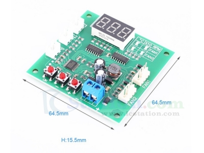
1.Description:
It is a PWM 4-Wire Fan Temperature Controller.It has a temperature and speed display and a stall alarm.
2.Feature:
1>.Digital display
2>.Wide operating voltage
3>.Dual independent temperature control
4>.Support button setting
5>.Stall alarm function
3.Parameter:
1>.Product Name:PWM 4-Wire Fan Temperature Controller
2>.Work Voltage:DC 8V~60V
3>.Control Board Working Current:35mA(12V),22mA (24V)
4>.Control Output Range:10%~100%
5>.Temperature Probe Specification:NTC 10KB=3950
6>.Temperature Measurement:-9.9℃~99.9℃
7>.Acceleration Temperature:5℃~94℃,
8>.Full Speed Temperature:10℃~99℃
9>.Speed Measurement:10rpm~9990rpm
10>.Stall Alarm Speed:<375rpm
11>.Work Temperature:-25℃~85℃
12>.Work Humidity:5%~95%RH
13>.Szie:64.5*64.5*15.5mm
4.Speed Resolution:
1>.10rpm at >9990rpm(the display show "999")
2>.Speed measurement is designed according to common 2-pole signal fans, most fans are 2-pole signals.
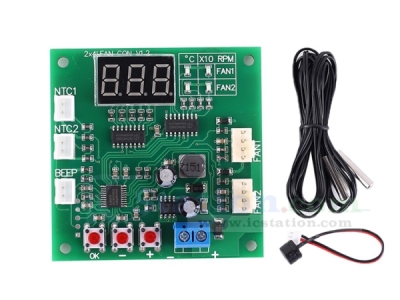
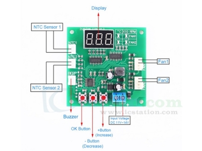
5.Wiring Instructions:
1>.The blue screw terminal is connected to the main power supply (the power supply voltage is equal to the fan voltage used,and it is in the range of 8V~60V).Please note that the positive and negative polarities are not connected incorrectly.
2>.The two 4P sockets of "channel 1" and "channel 2" are connected to the fan.The line sequence is power negative, power positive, speed feedback, PWM control.
3>."Thermal 1" and "Thermal 2" are connected to the NTC thermistor (parameter is 10KB= 3950),and the temperature is controlled by the temperature control of two channel fans.
4>.The "buzzer" socket is connected to the AC buzzer.When the stall alarm is turned on,the fan stall buzzer will beep long.
5>.The permissible current of a single fan interface is 3A.If you need to control a higher current fan,please connect the fan power cable directly to the main power supply (the controller's control capability has nothing to do with the fan current, but only the current passing ability of the power lead) must be considered.
6.Display Instruction:
1>.The control board displays the value through the display screen.The current value of the four LED indicators on the right side of the display screen indicates that the two LEDs on the first line indicate the temperature and speed of the channel 1 (x10rpm),and the two LEDs on the second line represent the channel two Temperature and speed (x10rpm).
2>.Under normal working conditions,the four values ??will be displayed in turn.You can quickly switch the value manually by pressing the + Button and - Button at any time.After manual switching,you will stay at this value for a long time before entering the wheel display state.You can shield the display of channel 2 as needed.
7.Setting Instructions:
1>.Basic speed setting:
1.1>.The basic speed setting is used to adjust the fan speed before the temperature control starts, that is,the fan speed when the temperature is lower than the acceleration temperature.
1.2>.The setting method is to press the "OK" button in any running state. At this time,two LEDs on the channel are lit at the same time. The digital tube displays the current setting value (between 10-100). ”Button to set the size, press and hold the button for quick and continuous modification.
1.3>.After setting,short press the "OK" button to enter the basic speed setting of channel 2.After setting in the same way, short press the "OK" button again to save and exit.
2>.Temperature control temperature zone and stall alarm setting:
2.1>.Under normal operation,long press the "OK" Button until "L**" is displayed (** is the value) and then release the button.The two LEDs on the channel 1 will light up at the same time.The "+" Button and "-" Button set this value (the range is 5℃~94℃).
2.2>.After setting,short press the "OK" Button to enter the channel 1 full speed temperature setting state,which is displayed as "H**".Set the amount in the same way (the range is 10℃~99℃).
2.3>.After setting,short press the "OK" Button to enter the channel 1 stall alarm setting, and the "+" Button and "-" Button to set,"boF" means turn off the channel stall alarm and "bon" means turn on the channel stall alarm.
2.4>.After setting,short press the "OK" Button to enter the value setting of channel 2,the sequence and setting method are the same as those of channel 1.
2.5>.When the above settings are completed,short press the "OK" Button to exit and save the parameters.
3>.Channel 2 display shielding setting:
3.1>.When the control board is powered off,press and hold the "OK" Button and keep the power on while holding down.The display shows "2on" (open channel 2 display) or "2oF" (shielded channel 2 display),and release "OK".Then press the button to set the switch shielding by the "+" Button and "-" Button.
3.2>.After setting,short press the "OK" button again to exit and enter the normal working state.
4>.Conventional timing and a counter mode switching:
4.1>.Without the fan connected, when the controller is not powered on, press and hold (note that it is kept pressed) the "+" Button and "-" Button to power the controller.At this time,the controller enters the mode selection state and releases the button.
4.2>.Click the "+" Button or "-" Button again to switch the mode:"F-1" is displayed as the normal mode,and "F-2" is displayed as the reverse timing mode.
4.3>.After modification,click the "OK" button to exit (automatically save on exit) settings.
6>.
8.Setting Note:
1>.In the setting state of speed and temperature zone,if there is no operation after 15 seconds,it will exit automatically without saving data.
2>.When setting the temperature zone,the full-speed temperature of the same channel must be at least 5 degrees Celsius higher than the acceleration temperature.When setting a temperature value that causes this condition to be unsatisfactory,the controller will automatically adjust another temperature value to ensure that the difference is not low.In the condition of 5 degrees Celsius,this automatic adjustment is one-way,if you need to call back,you need to manually adjust another temperature value.
3>.The shielding display setting of channel 2 only affects the data display of the working state. The control and parameter setting of channel 2 have no effect and work normally.
9.Common Problem Description:
1>.No display after power on:The voltage is not suitable, and the power supply is reversed.The controller can run under DC8-60V input.Please make sure that the power supply voltage and polarity are correct.
2>.The temperature display always shows -9.9℃, the actual temperature is not so low,or the displayed temperature is very different from the actual temperature:The corresponding channel probe is not connected, the probe is in bad contact or damaged, and the probe parameters are incorrect-check the probe.
3>.The fan does not turn:
3.1>.Fan wire sequence error: Please pay attention to the fan wire sequence power cord.
3.2>.Some fans will stop when the PWM value is lower than 20: increase the manual speed adjustment value.
4>.The fan runs at full speed, cannot be controlled, and the speed is not displayed:
4.1>.Fan wire sequence error (speed measurement line and control line are reversed):exchange the control line and speed measurement line of the fan (two lines other than the power line).
4.2>.Fan unconventional PWM fan,fake or shoddy,or fan failure: Replace the fan
5>.The fan can be controlled normally, but the speed is not displayed:
5.1>.Fan speed line (third line) is not reliably connected: check the wiring
5.2>.The fan does not have a speed measurement signal or the fan speed output port is faulty: replace other fans or ignore the speed display
6>.Fan speed reverse:The fan is an anti-sequence fan, which modifies the controller operating mode.
10.Note:
1>.The working voltage must be equal to the fan voltage. If you use a 12V fan but supply 24V, it will burn the fan.
2>.This product is not limited by the fan current,but the pin current of the fan interface on the board should not be greater than 3A. If you use a higher current fan, please connect the fan power cord directly to the main power.
11.Package:
1>.1pcs PWM 4-Wire Fan Temperature Controller
2>.1pcs NTC Temperature Sensor
3>.1pcs Buzzer
| Quantity | 60+ |
| Price | $6.40 |
ICStation doesn't accept any form of pay on delivery. Items used to be shipped after payment. Below are the payment methods we can accept at the moment:
1) Paypal Payment
PayPal is a secure and trusted payment processing service that allows you to shop online. PayPal can be used at icstation.com to purchase items by Credit Card (Visa, MasterCard, Discover, and American Express), Debit Card , or E-check (i.e. using your regular Bank Account).

We are PayPal Verified 
2) Bank Transfer / Wire Transfer / T/T
Bank Transfer / Wire Transfer / T/T payment methods are accepted for orders which the total price is up to US$300. The bank will charge about US$50 for the transfer fee if we do the payment in these ways. Feel free to contact us for bank payment details if you need pay via bank.
For other payment method, please contact us at orders@icstation-team.com for more details.